An auxiliary switch control structure and a switch cabinet having the same

An auxiliary switch and installation structure technology, applied in the direction of electrical switches, electrical components, circuits, etc., can solve the problems of unable to form stable cooperation, affecting the safety of equipment, etc., and achieve the effects of stable cooperation, good linkage and high installation efficiency.

Active Publication Date: 2019-02-19
ZHEJIANG LINGAO ELECTRICAL IND
View PDF8 Cites 0 Cited by
  • Summary
  • Abstract
  • Description
  • Claims
  • Application Information

AI Technical Summary

Problems solved by technology

[0004] Therefore, the technical problem to be solved by the present invention is to overcome the control structure of the auxiliary switch in the prior art. During the installation process, a very precise installation distance needs to be maintained between the fan-shaped plate and the auxiliary contact of the auxiliary switch. Once the fan-shaped plate and the auxiliary switch The relative positions of the two parts cannot be accurately matched, and the two will not be able to form a stable cooperation, which will affect the safety of the equipment, so as to provide an auxiliary switch control structure with low precision requirements, stable cooperation and good linkage during installation.

Method used


Image

  • An auxiliary switch control structure and a switch cabinet having the same
  • An auxiliary switch control structure and a switch cabinet having the same
  • An auxiliary switch control structure and a switch cabinet having the same

Examples


Embodiment 1

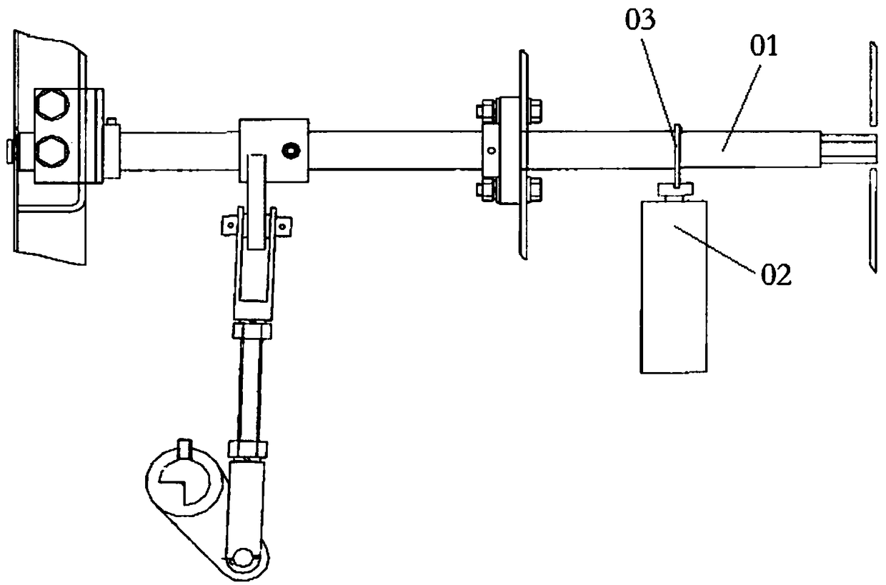
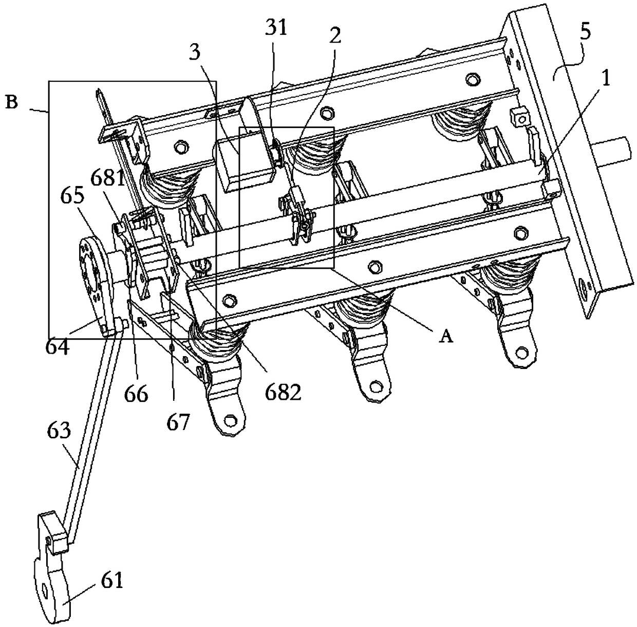
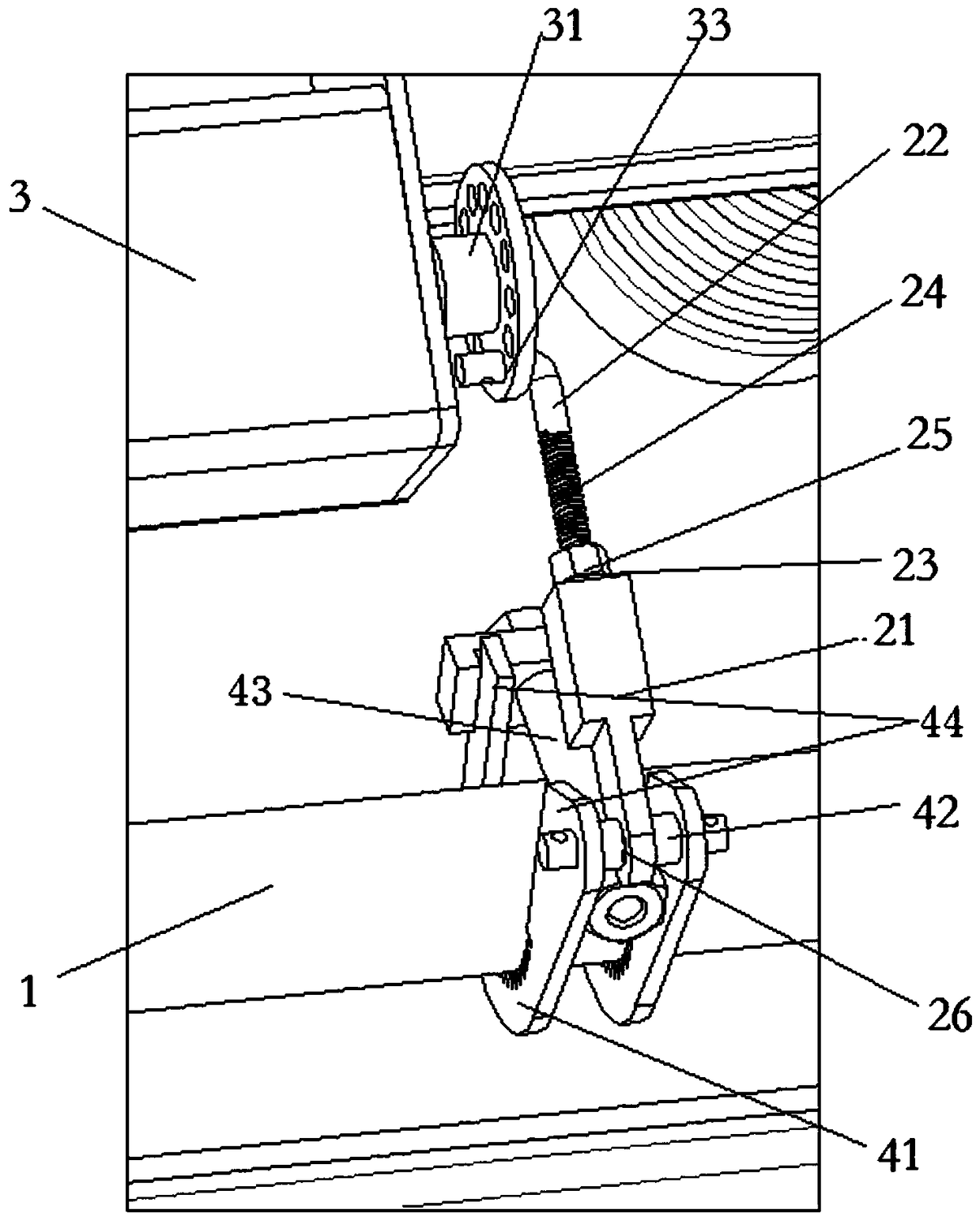
[0057] This embodiment provides an auxiliary switch control structure, such as Figure 2-3 As shown, it includes: a driving rod 1, which can rotate around its own axis under the action of an external force; a linkage rod 2, whose axial length is adjustable, one end is rotatably connected to the driving rod 1 through a mounting structure, and the other end is connected to the opening and closing gate. The turntable 31 is connected, and the opening and closing turntable 31 is used to drive the auxiliary switch 3 to connect the closing circuit or the opening circuit; when the driving rod 1 rotates, it drives the movement of the linkage rod 2, and then drives the opening and closing circuit. The turntable 31 rotates to control the auxiliary switch 3 to connect the closing circuit or the opening circuit.

[0058] In the auxiliary switch control structure of this embodiment, after the drive rod 1 and the auxiliary switch 3 are installed respectively, the linkage rod 2 is used to con...

Embodiment 2

[0068] This embodiment provides a switchgear, such as Image 6 and refer to as Figure 1-5 As shown, the switchgear of this embodiment includes the auxiliary switch control structure as described in Embodiment 1.

[0069] Because the switchgear of this embodiment includes the above-mentioned auxiliary switch control structure, it naturally has all the advantages brought by the above-mentioned control structure.


PUM


Abstract

The invention provides an auxiliary switch control structure and a switch cabinet with the same. The control structure comprises a drive rod and a linkage rod, wherein the drive rod can rotate around the axis under the effect of external force, the axial length of the linkage rod is adjustable, one end of the linkage rod is rotationally connected with the drive rod through an installation structure, the other end of the linkage rod is connected with a switching-on and switching-off rotating plate, the switching-on and switching-off rotating plate is used for driving an auxiliary switch to close a switching-on circuit or a switching-off circuit; when the drive rod rotates, the linkage rod is driven to move, and then the switching-on and switching-off rotating plate is driven to rotate, so that the auxiliary switch is controlled to close the switching-on circuit or the switching-off circuit. Due to the fact that the axial length of the linkage rod are adjustable, and the requirement for the installation distance between the drive rod and the auxiliary switch is not strict during installation, the installation efficiency is high; the two ends of the linkage rod are connected with the drive rod and the switching-on and switching-off rotating plate respectively, compared with an installation mode corresponding to a sector plate and an auxiliary contact in the prior art, cooperation is more stable, and linkage is good.

Description

technical field [0001] The invention relates to the technical field of switch cabinet equipment, in particular to an auxiliary switch control structure and a switch cabinet having the same. Background technique [0002] Auxiliary switch is a kind of switchgear in the switchgear, often used in conjunction with the load switch, and can transmit the opening and closing signal of the load switch to other equipment. The auxiliary switch is associated with the load switch. When the load switch is in the closing state, the auxiliary contact of the auxiliary switch is connected to the circuit where the load switch closing indicator light is located, and the load switch closing indicator light is on; when the load switch is in the opening state, the auxiliary contact The auxiliary contact of the switch is connected to the circuit where the load switch opening indicator light is located, and the load switch opening indicator light is on. The staff can intuitively know the working sta...

Claims


Application Information

Patent Timeline
Patent Type & Authority Patents(China)
IPC IPC(8): H01H9/16H01H9/24
CPCH01H9/161H01H9/24
Inventor 凌斯
Owner ZHEJIANG LINGAO ELECTRICAL IND
Why Eureka
Try Eureka