Operating mechanism of electric switch

A technology of electrical switch and operating mechanism, which is applied in the direction of protection switch operation/release mechanism, parts of protection switch, electrical components, etc., and can solve the problems of withstand voltage breakdown, non-isolation, slow breaking speed, etc.

Active Publication Date: 2017-05-31
温州奥来电器有限公司
View PDF7 Cites 2 Cited by
  • Summary
  • Abstract
  • Description
  • Claims
  • Application Information

AI Technical Summary

Problems solved by technology

[0002] The operating mechanism of the existing electric switch generally adopts the following method, the moving contacts of the L pole and the N pole are respectively fixed on the L pole and N pole moving contact brackets, and then the L pole and N pole moving contact brackets are arranged on the lever On both sides, the lock and jumper are also set on the lever. At this time, the mechanism is bulky, the movement of the mechanism is not flexible, and the breaking speed is slow. The moving contacts of L pole and N pole are respectively located on the upper and lower sides of the middle seat. N-pole movable contact brackets are set on both sides of the lever, and the L-pole and N-pole of the mechanism part cannot be isolated. When breaking a large current, the arc and conductive gas are easily shorted, causing the product to burst and fail to break the product.
And there is a risk of withstand voltage breakdown after breaking, which cannot meet the user's requirements

Method used


Image

  • Operating mechanism of electric switch
  • Operating mechanism of electric switch
  • Operating mechanism of electric switch

Examples


Embodiment Construction

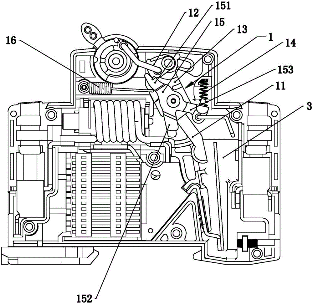
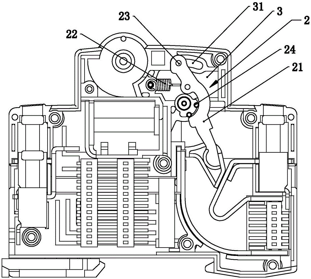
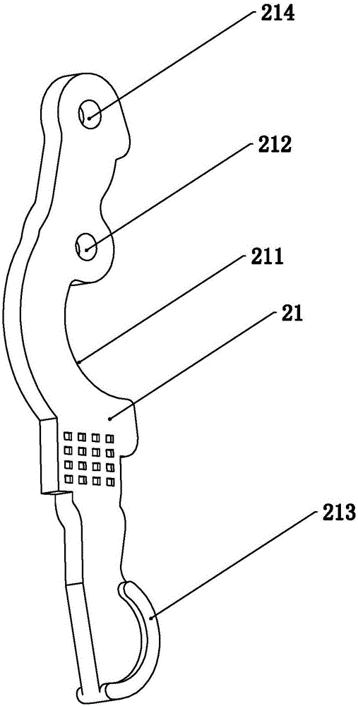
[0024] Such as Figure 1-8 As shown, an operating mechanism of an electric switch includes an L pole operating device 1, wherein the L pole operating device 1 includes an L pole moving contact 11, a jumper 12, an L pole moving contact bracket 13, and a lock spring 14 , the lock 15 and the first tension spring 16, wherein the L pole moving contact 11 is fixedly arranged on the moving contact bracket 13, and the L pole moving contact bracket 13 is provided with a long through hole, and a pin shaft is arranged in the long through hole , the two ends of the pin are arranged on the middle seat 3 and the upper cover of the electric switch, and one end of the first tension spring 16 is connected to the L pole moving contact bracket 13, and the connection with the L pole moving contact bracket 13 The point is located above the long through hole, and the other end of the first tension spring 16 is fixedly connected to the middle seat 3 of the electric switch or other parts fixedly conn...


PUM


Abstract

The invention relates to an electric switch, namely, a breaker, in particular to an operating mechanism for operating a switch to be switched on or switched off in the electric switch. The operating mechanism in the technical scheme is characterized in that an N-pole operating device is also arranged between a middle base and a base of the electric switch, and comprises an N-pole moving contact, a second tension spring, a connecting shaft and abutting against pins, the connecting shaft is arranged in a long hole in the upper portion of the middle base of the electric switch, an arc abutting against face is arranged in the middle of the N-pole moving contact, the abutting against pins are arranged between the middle base and the base of the electric switch, the abutting against pins and the arc abutting against face are correspondingly arranged, one end of the second tension spring is connected on a connecting hole or a connecting boss, the other end of the second tension spring is connected on the middle base or the base of the electric switch. According to the technical scheme, the novel operating mechanism of the electric switch is good in voltage-resistant effect during disjunction, and product explosion is not prone to occurrence.

Description

technical field [0001] The invention relates to an electrical switch, also called a circuit breaker, in particular to an operating mechanism for closing or disconnecting an operating switch in the electrical switch. Background technique [0002] The operating mechanism of the existing electric switch generally adopts the following method, the moving contacts of the L pole and the N pole are respectively fixed on the L pole and N pole moving contact brackets, and then the L pole and N pole moving contact brackets are arranged on the lever On both sides, the lock and jumper are also set on the lever. At this time, the mechanism is bulky, the movement of the mechanism is not flexible, and the breaking speed is slow. The moving contacts of L pole and N pole are respectively located on the upper and lower sides of the middle seat. N-pole movable contact brackets are arranged on both sides of the lever, and the L-pole and N-pole of the mechanism part cannot be isolated. When break...

Claims


Application Information

Patent Timeline
Patent Type & Authority Applications(China)
IPC IPC(8): H01H71/10H01H73/04
CPCH01H71/10H01H73/04H01H71/0214H01H71/002
Inventor 王亮华
Owner 温州奥来电器有限公司
Why Eureka
Try Eureka