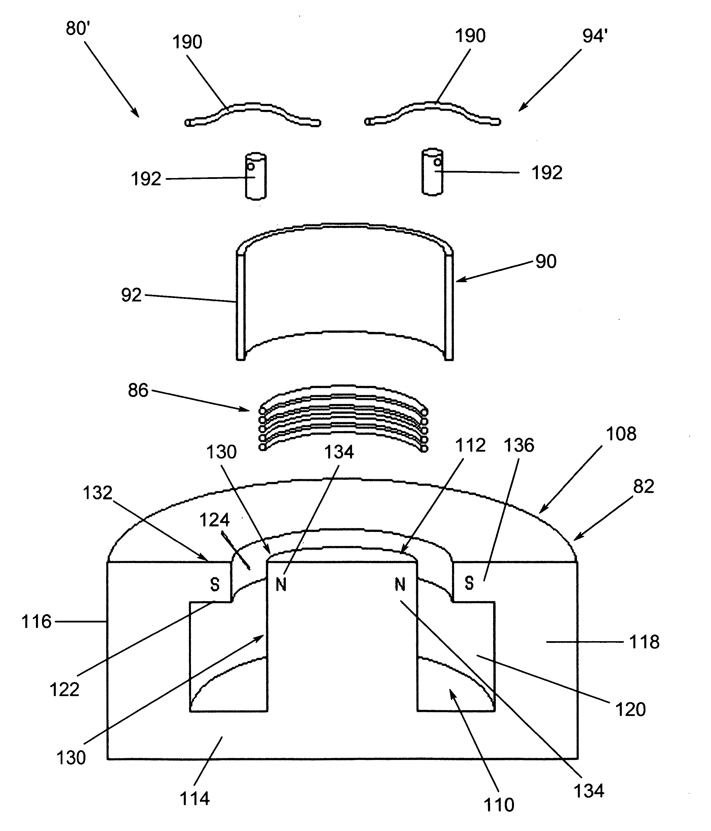
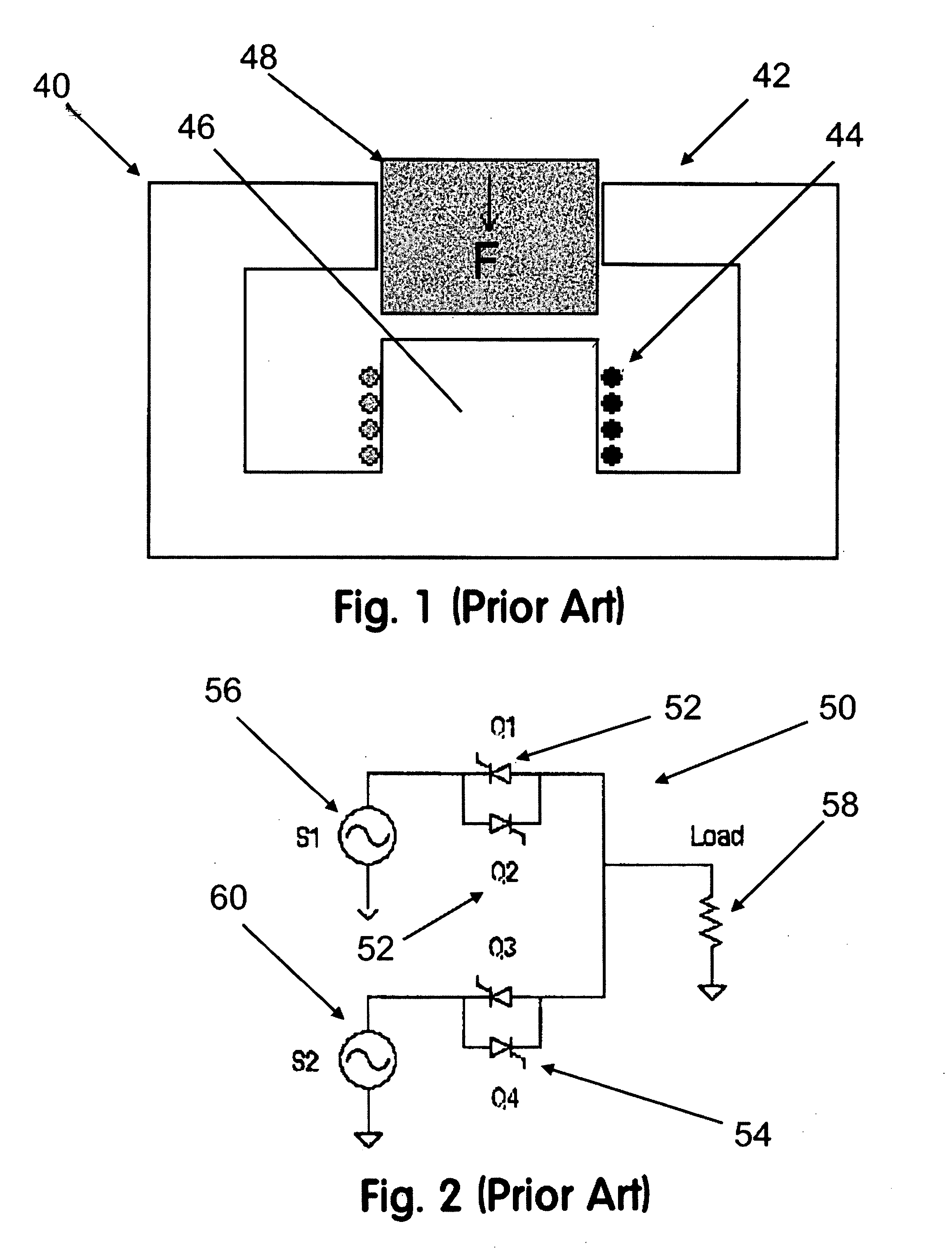
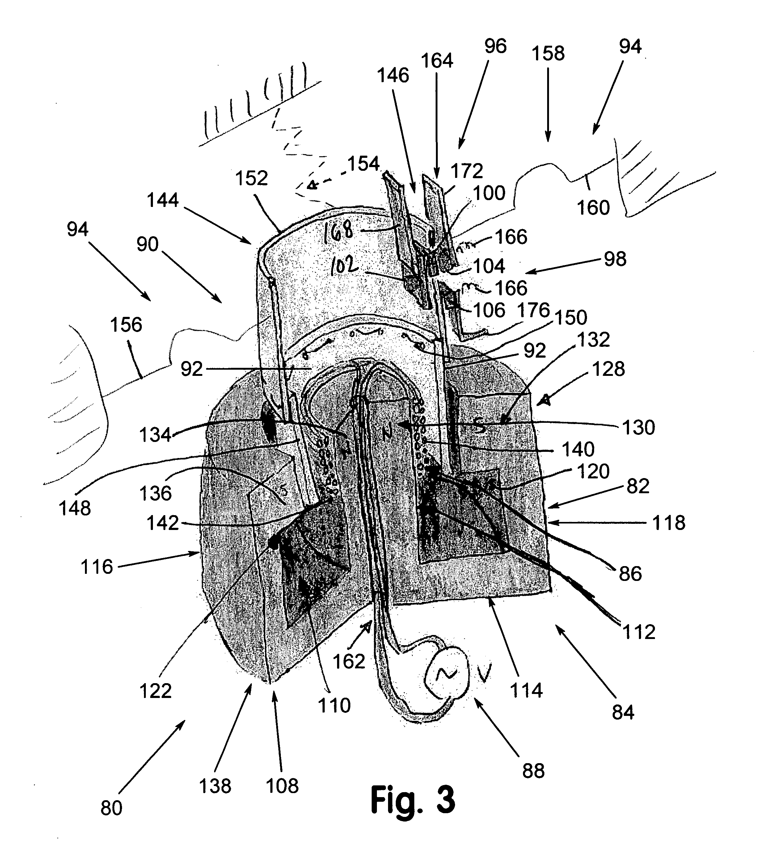
Unfortunately, due at least in part to its relatively high
inertia armature construction, solenoid actuators 40 have undesirably
slow response times, which limits switching speeds and transfer times when used in electromechanical transfer switches.
However, these electromechanical
transfer switch actuators do nothing to remedy the deficiencies found in the aforementioned solenoid actuators.
In fact, these types of actuators are often part of a relatively complex
transfer switch mechanism that includes cams, gears, linkages and the like.
Not only are such
transfer switch mechanisms unacceptably slow for more demanding transfer switch applications, their components can undesirably wear over time or even stick, if not frequently tested, resulting in premature or even unexpected failure.
For example, conventional solenoid actuators and rotary
stepper motor actuators in the past have been inherently slow operating, limiting their use to switching applications tolerant of their slow switching speeds and slow transfer times.
With specific regard to automatic transfer switching applications, it has been a challenge to achieve transfer times faster than about seven
alternating current cycles, e.g., less than 120 milliseconds where sixty
hertz alternating current is used, using a transfer switch that is electromagnetically actuated.
As a result, electromagnetically actuated automatic transfer switches have been limited to less critical switching applications, such as those where the load can tolerate up to five cycles of
power loss during switching.
Unfortunately, SCRs have certain disadvantages.
For example, SCRs dissipate more power than electromechanically actuated transfer switches sometimes producing a significant amount of heat during operation.
As a result, cost and complexity is often increased as additional equipment may be needed to remove the heat produced by the SCRs.
Where
heat transfer equipment is needed, transfer switch maintenance and monitoring costs typically are undesirably increased.
Another drawback lies in the fact that SCRs always require a supply of
control power to maintain connection between an input source and the load.
Unfortunately, the level of redundancy typically required to ensure reliable and stable operation undesirably increases its purchase price, adds to complexity, and requires additional monitoring and maintenance, all of which is undesirable and adds to overall
operational costs.
A still further drawback lies in the fact that an SCR cannot be turned off by simply telling it to “turn off” or by sending it a “turn off”
signal.
In certain instances when trying to turn an SCR off, it can take an unacceptably long time for the current to drop low enough for the SCR to actually turn off and break the flow of power to the load.
Sometimes, this
delay can leave the load without power or sufficient quality power, which can adversely affect load operation.
In some cases, its operation can cease and damage can occur.
This inability to turn off an SCR under electronic control in a predictable, repeatable, and consistent manner also makes it difficult to guarantee that current flow to the load from one input source will be switched off before current flow from the other input source is switched on.
Should current flow from both input sources end up being provided to the load at the same time, such as what can happen if the control current does not reach a low enough value to cause the SCRs connected to the one input source to switch off in time before the other SCRs turn on connecting the load to the other input source, both input sources can end up becoming shorted together.
Even though this might happen for only a relatively short period of time, this kind of short circuiting can damage the transfer switch, can adversely
impact operation of the load, can adversely affect other loads connected elsewhere to one or both input sources, and can even cause both input sources to catastrophically fail, leading to complete
power loss.
This type of short circuiting is more commonly known as cross-conduction or
shoot-though, and is a well-known failure mode of
solid-state transfer switches.
To attempt to prevent this,
solid state automatic transfer switches often have a great deal of built-in redundancy and typically require relatively complex control circuitry and
control logic.
As a result, cost is undesirably increased and their required complexity alone compromises reliability.
Where used for particularly critical transfer switching applications, monitoring, testing and maintenance requirements are more stringent and costly, all of which is undesirable.
Finally, because of packaging size constraints, SCRs, as with any type of
solid state switch, are simply not able to meet certain international
safety standards because their terminals are inherently spaced too close together.
Where these and other similarly stringent standards come into play,
solid state switches typically cannot be used.
While there are other types of
solid state switches, their limitations are so great that they have found, at best, only limited use in transfer switches.
However, they all generally suffer from unacceptably high conduction losses in
high current and
high voltage applications, such as what is frequently encountered in transfer switching applications.
In addition, they typically are not robust enough for most, if not virtually all, static transfer switch applications.
For example, these types of
semiconductor switches are often unable to withstand high short-circuit currents without failing or undesirably degrading in performance.


