Electrical switching apparatus, and charging assembly and interlock assembly therefor

a technology of electrical switching apparatus and charging assembly, which is applied in the direction of circuit-breaking switches, circuit-breaking switches, and snap-action arrangements, etc., which can solve the problems of unintentional release of charging handle, damage to one or more components of closing assembly and/or charging assembly, and possible existen

Active Publication Date: 2009-04-14
EATON INTELLIGENT POWER LTD
View PDF7 Cites 42 Cited by
  • Summary
  • Abstract
  • Description
  • Claims
  • Application Information

AI Technical Summary

Benefits of technology

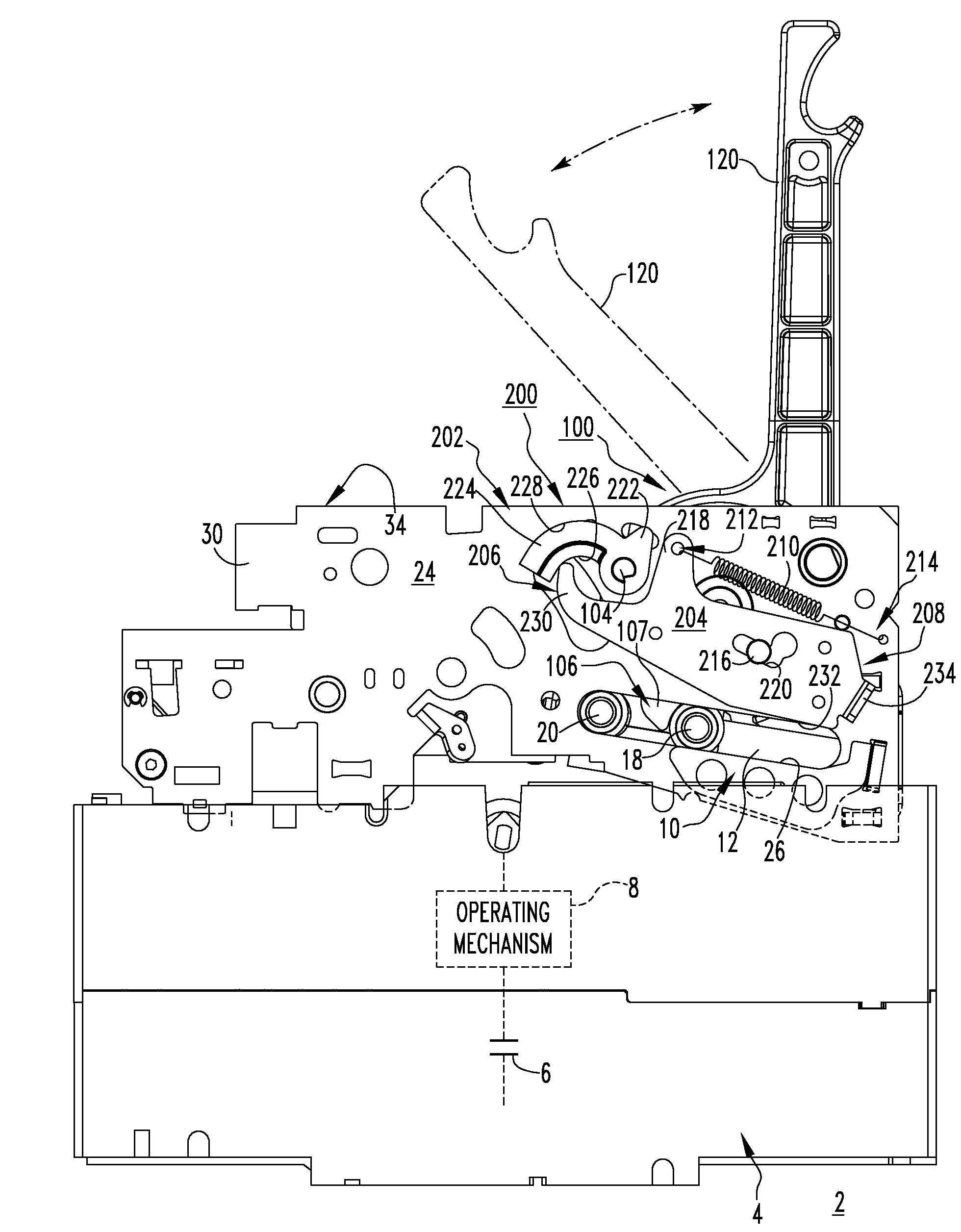
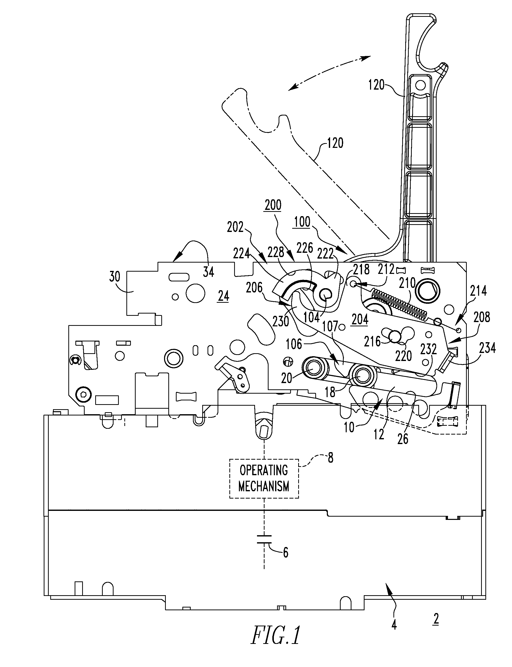
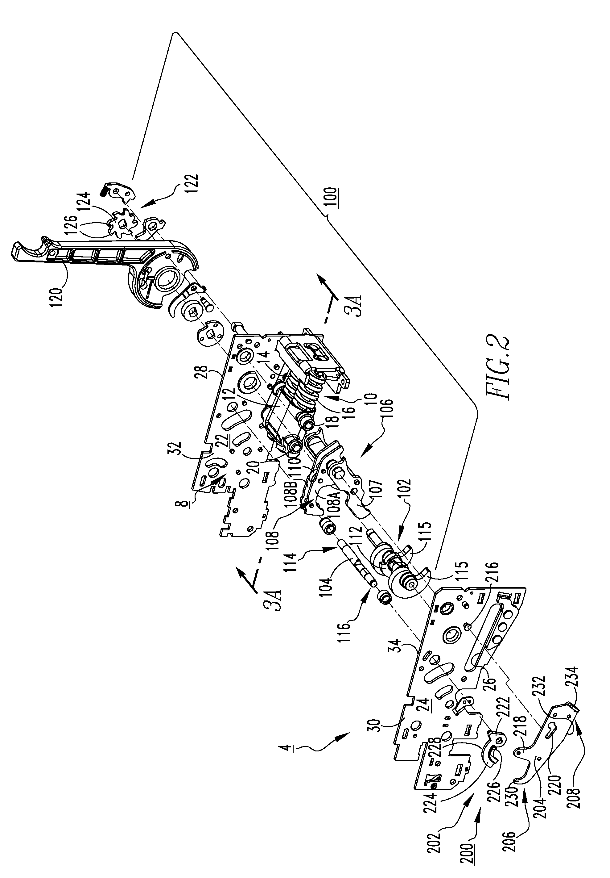
[0009]These needs and others are met by embodiments of the invention, which are directed to an interlock assembly for the charging assembly of an electrical switching apparatus, such as a circuit breaker. The interlock assembly resists damage potentially caused by the unintentional release of energy stored in the stored energy mechanism (e.g., without limitation, closing spring(s)) of the closing assembly, for example and without limitation, in the event the charging handle of the charging assembly is unintentionally released (e.g., without limitation, accidentally dropped) while an operator is manually charging the circuit breaker.

Problems solved by technology

During the manual charging operation, the possibility exists that the charging handle could be unintentionally released (e.g., without limitation, accidently dropped).
Under such circumstances, depending on the position of the charging handle, energy that has already been stored (e.g., closing spring(s) partially charged) could be suddenly released, causing damage to one or more components of the closing assembly and / or charging assembly.

Method used


Image

  • Electrical switching apparatus, and charging assembly and interlock assembly therefor
  • Electrical switching apparatus, and charging assembly and interlock assembly therefor
  • Electrical switching apparatus, and charging assembly and interlock assembly therefor

Examples


Embodiment Construction

[0025]For purposes of illustration, embodiments of the invention will be described as applied to medium and low voltage circuit breakers, although it will become apparent that they could also be applied to the charging assemblies of any known or suitable electrical switching apparatus (e.g., without limitation, circuit switching devices and circuit interrupters such as circuit breakers other than medium and low voltage circuit breakers, network protectors, contractors, motor starters, motor controllers and other load controllers).

[0026]Directional phrases used herein, such as, for example, clockwise, counterclockwise, left, right, top, bottom, up, down and derivatives thereof, relate to the orientation of the elements shown in the drawings and are not limiting upon the claims unless expressly recited therein.

[0027]As employed herein, the statement that two or more parts are “coupled” together shall mean that the parts are joined together either directly or joined through one or more...


PUM


Abstract

An interlock assembly is provided for a circuit breaker charging assembly. The charging assembly includes a cam shaft, a latch mechanism, such as a D-shaft, a latch assembly, and a charging handle. The charging handle pivots the cam shaft. The D-shaft is pivotable between first and second positions corresponding to the D-shaft latching and unlatching the latch assembly, respectively. The interlock assembly includes a lever coupled to and pivotable with the D-shaft, and a latch interlock pivotably coupled to the circuit breaker housing. The latch interlock moves between locked and unlocked positions corresponding respectively to the first end of the latch interlock moving the lever to position the D-shaft in the second position and the first position. Unless and until the stored energy mechanism is substantially fully charged, the latch interlock is disposed in the locked position and the latch assembly is movable with respect to the D-shaft.

Description

BACKGROUND OF THE INVENTION[0001]1. Field of the Invention[0002]The invention relates generally to electrical switching apparatus and, more particularly, to electrical switching apparatus, such as circuit breakers. The invention also relates to charging assemblies for electrical switching apparatus. The invention further relates to interlock assemblies for the charging assemblies of electrical switching apparatus.[0003]2. Background Information[0004]Electrical switching apparatus, such as circuit breakers, provide protection for electrical systems from electrical fault conditions such as, for example, current overloads, short circuits, abnormal voltage and other fault conditions. Typically, circuit breakers include an operating mechanism, which opens electrical contact assemblies to interrupt the flow of current through the conductors of an electrical system in response to such fault conditions as detected, for example, by a trip unit. The electrical contact assemblies include stati...

Claims


Application Information

Patent Timeline
Patent Type & Authority Patents(United States)
IPC IPC(8): H01H5/00
CPCH01H3/3005H01H9/20H01H2003/3057
Inventor GOTTSCHALK, ANDREW L.RAKUS, PAUL R.
Owner EATON INTELLIGENT POWER LTD
Why Eureka
Try Eureka