
Assembly mold and assembly method for composite tube shell spiral line slow-wave structure

A slow-wave structure and composite tube-shell technology, which can be used in the manufacture of ships or lead-in wires, etc., can solve problems such as difficult assembly, and achieve the effects of strong operability, high clamping quality and low cost.

Active Publication Date: 2017-05-31
北京真空电子技术研究所
View PDF7 Cites 2 Cited by
  • Summary
  • Abstract
  • Description
  • Claims
  • Application Information

AI Technical Summary

Problems solved by technology

[0006] The second technical problem to be solved by the present invention is to provide an assembly method for assembling the helical slow-wave structure of the composite shell by using the above-mentioned assembly mold in addition to the traditional shell thermal expansion clamping method and cold clamping method; through the new The assembly method solves the problem of difficult assembly of the helical slow wave structure of the composite shell and improves the production efficiency of the helical slow wave structure of the composite shell

Method used


Image

  • Assembly mold and assembly method for composite tube shell spiral line slow-wave structure
  • Assembly mold and assembly method for composite tube shell spiral line slow-wave structure
  • Assembly mold and assembly method for composite tube shell spiral line slow-wave structure

Examples


Embodiment Construction

[0043] In order to illustrate the present invention more clearly, the present invention will be further described below in conjunction with preferred embodiments and accompanying drawings. Similar parts in the figures are denoted by the same reference numerals. Those skilled in the art should understand that the content specifically described below is illustrative rather than restrictive, and should not limit the protection scope of the present invention.

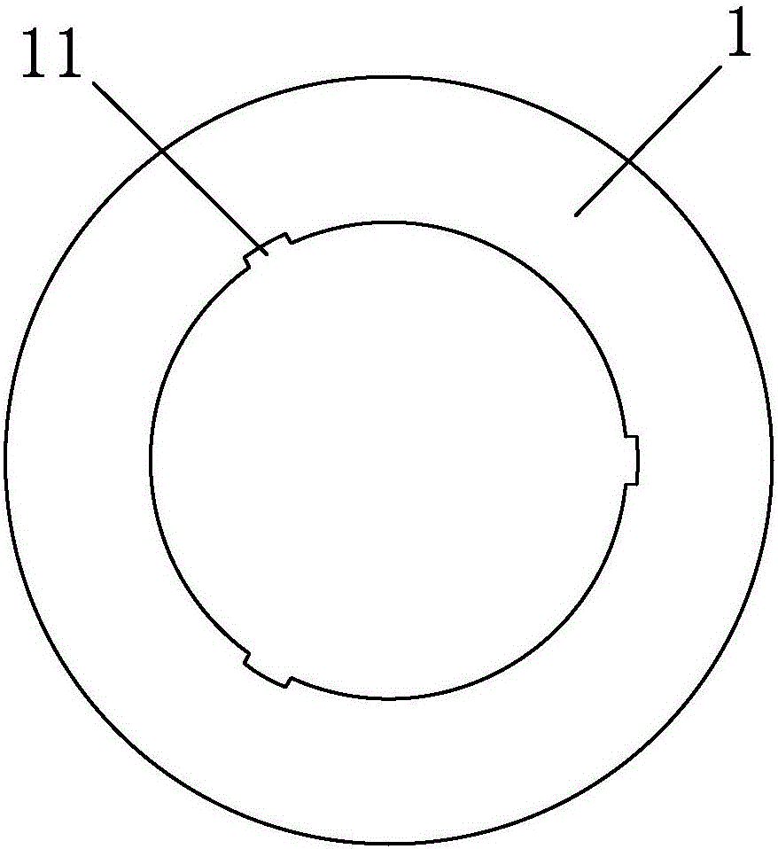
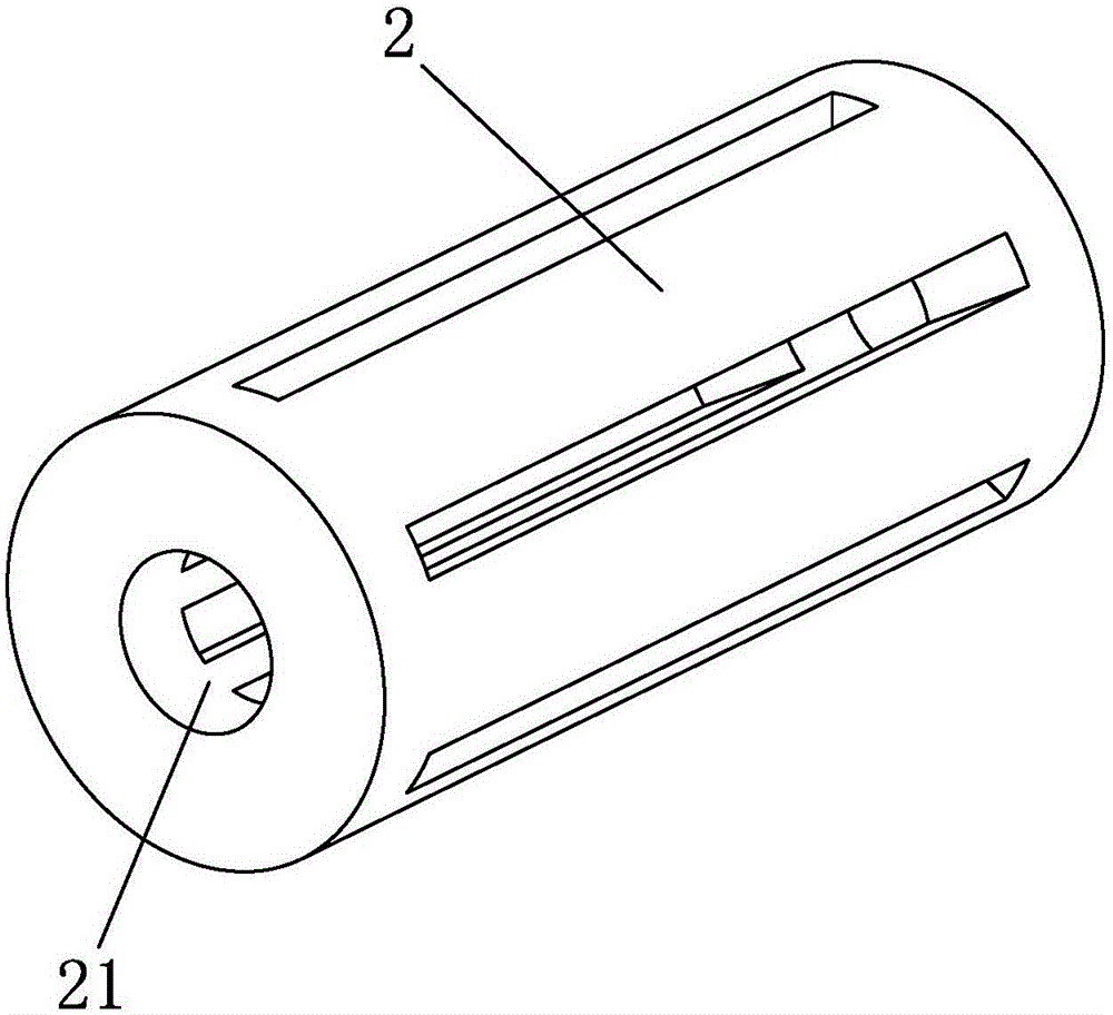
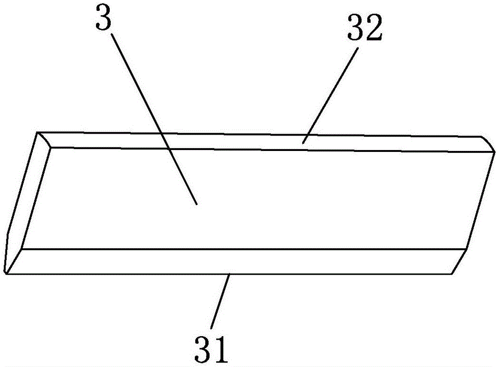
[0044] Such as Figures 1 to 11As shown, an assembly mold for a helical slow wave structure of a composite shell, the assembly mold includes a clamping assembly sleeved outside the helix 100, a support assembly set inside the helix 100, and a 100 is assembled into a mounting assembly within the composite casing 200;

[0045] The clamping assembly includes a tube body 1 in a circular tubular structure and a clamp for clamping and fixing the helix 100 arranged between the outer wall surface of the helix 100 and the inner wa...


PUM


Abstract

The invention discloses an assembly mold and an assembly method for a composite tube shell spiral line slow-wave structure. The assembly mold comprises a grasp module, a support component and an installation component. The grasp module comprises a tube body and a clamp. The clamp comprises a grip-body and a support rod. An internal end face of the support rod is utilized for supporting and pressing on an external wall face of the spiral line and an external end face of the support rod is utilized for supporting and pressing on an internal wall face of the tube body. The support component comprises a support shaft lever and a support shaft chuck. The support shaft chuck is disposed between two adjacent support rods which make the spiral line have elastic deformation. The installation component comprises a first member bar and a second member bar. According to the deformability of the spiral, through the cooperation among assembly molds and spiral lines, the assembly of the composite tube shell spiral line slow-wave structure is achieved.

Description

technical field [0001] The invention belongs to the field of microwave vacuum electronic devices, and in particular relates to an assembly mold and an assembly method for a helical slow wave structure of a composite shell. Background technique [0002] At present, domestic broadband miniaturized traveling wave tubes generally adopt a traditional high-frequency structure, which consists of a shell with internal loading ribs, a helix, a ceramic rod, and peripheral pole pieces and backing rings. Due to the existence of the shell of this kind of high frequency structure, the utilization rate of magnetic flux is low, the volume of the magnetic focusing system increases, and due to the size limitation of the shell and the backing ring, the high frequency system will become a weak link of the whole tube of the traveling wave tube, which directly affects reliability of the manufacturing process. However, the miniaturized phase-coherent traveling wave tube imported from abroad adopt...

Claims


Application Information

Patent Timeline
Patent Type & Authority Applications(China)
IPC IPC(8): H01J9/24
CPCH01J9/24
Inventor 崔建玲张雪利陈曦曹绅
Owner 北京真空电子技术研究所
Learn More