
Module type permanent magnet motor rotor with radial ventilation channel and motor

A technology of radial ventilation and permanent magnet motors, applied in the direction of magnetic circuit rotating parts, electrical components, electromechanical devices, etc., can solve the problem that it is difficult for permanent magnets to form gaps, permanent magnets cannot be repaired or replaced, and the contact area between cooling air and motors Limited and other problems, to reduce maintenance costs and improve the effect of internal ventilation

Pending Publication Date: 2017-05-31
XIANGTAN ELECTRIC MFG CORP LTD
View PDF3 Cites 1 Cited by
  • Summary
  • Abstract
  • Description
  • Claims
  • Application Information

AI Technical Summary

Problems solved by technology

[0002] Usually, permanent magnet motors are generally cooled by axial forced ventilation, and only heat exchange is performed in the air gap between the stator and rotor. The contact area between the cooling air and the motor is very limited. The rotor poles of permanent magnet motors include magnetic pole cores and permanent magnets. Permanent magnet motors Due to the existence of mutual repulsion between permanent magnets in the axial direction, the permanent magnets must rely on the magnetic pole pressure plates at both ends to compress the permanent magnets in the axial direction, so that it is difficult to form a gap between the permanent magnets. The magnets are interdependent and fixed. If a permanent magnet needs to be repaired or replaced, all the permanent magnets must be removed, so it is impossible to repair or replace a single permanent magnet.

Method used


Image

  • Module type permanent magnet motor rotor with radial ventilation channel and motor
  • Module type permanent magnet motor rotor with radial ventilation channel and motor
  • Module type permanent magnet motor rotor with radial ventilation channel and motor

Examples


Embodiment Construction

[0016] The present invention will be further described below in conjunction with drawings and embodiments.

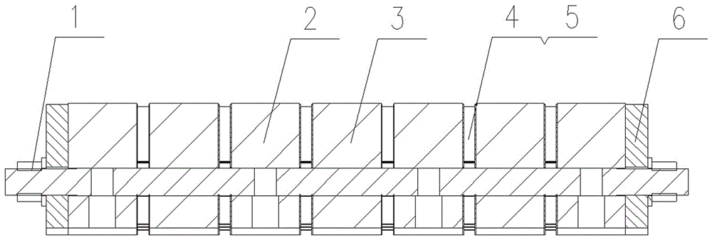
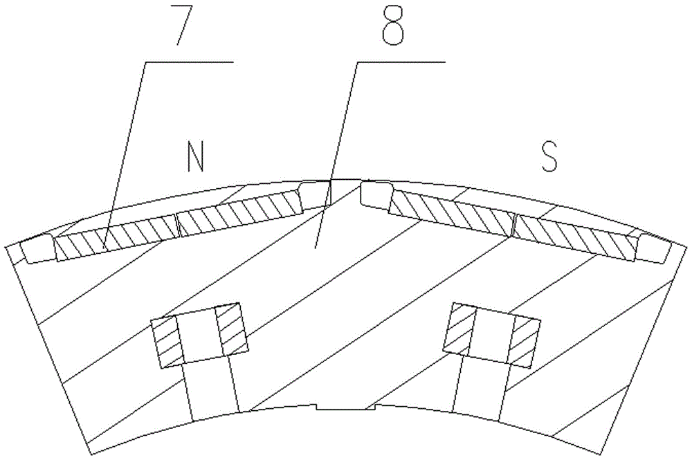
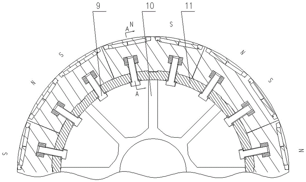
[0017] With reference to the accompanying drawings, a modular permanent magnet motor rotor with radial ventilation ducts includes magnetic poles, a rotating shaft 10 with ribbed plates, and a magnetic pole fixing ring 11. The magnetic poles include a magnetic pole core 8, a permanent magnet 7, and a magnetic pole fixing ring 11. Set on the outer circle of the rotating shaft 10 of the ribbed plate, the magnetic pole is divided into eight modular magnetic poles from the radial direction, and the modular magnetic pole includes a magnetic pole, a magnetic pole pressure plate 6, a tension screw pair 1, and a ventilation groove plate 4. The pole core 8 is divided into seven pole core units in the axial direction, including four pole core units 2 with installation holes and three pole core units 3 without installation holes. Adjacent poles Ventilation slots 4 and ventilation s...


PUM


Abstract

The invention relates to a module type permanent magnet motor rotor with radial ventilation channels. A Magnetic pole is equally divided into two or more than two module type magnetic poles in a radial direction; a magnetic pole core is divided into two or more than two magnetic pole core units in an axial direction; ventilation channel plates and ventilation channel pieces among adjacent magnetic pole core units form radial ventilation channels of the module type magnetic poles; the module type magnetic poles are fixed with magnetic pole fixing rings through connecting bolts. As the magnetic poles are equally divided into two or more than two module type magnetic poles in the radial direction, and the radial ventilation channels formed by the ventilation channel plates and the ventilation channel pieces are formed in the module type magnetic poles in the axial direction, an internal ventilation effect of the permanent magnet motor can be greatly improved; in addition, as the module type magnetic poles are also divided into a plurality of magnetic pole core units in the axial direction, only single magnetic pole core units need to be replaced when being repaired and replaced. The invention further relates to a motor with the module type permanent magnet motor rotor with the radial ventilation channels.

Description

technical field [0001] The invention relates to a rotor in the field of motors, in particular to a modular permanent magnet motor rotor and a motor with radial air ducts. Background technique [0002] Usually, permanent magnet motors are generally cooled by axial forced ventilation, and only heat exchange is performed in the air gap between the stator and rotor. The contact area between the cooling air and the motor is very limited. The rotor poles of permanent magnet motors include magnetic pole cores and permanent magnets. Permanent magnet motors Due to the existence of mutual repulsion between permanent magnets in the axial direction, the permanent magnets must rely on the magnetic pole pressure plates at both ends to compress the permanent magnets in the axial direction, so that it is difficult to form a gap between the permanent magnets. The magnets are interdependent and fixed. If a certain permanent magnet needs to be repaired or replaced, all the permanent magnets mu...

Claims


Application Information

Patent Timeline
Patent Type & Authority Applications(China)
IPC IPC(8): H02K1/32H02K1/27H02K1/28
CPCH02K1/27H02K1/28H02K1/32H02K2213/12
Inventor 王步瑶王孝朋王振杨国伟雷向福
Owner XIANGTAN ELECTRIC MFG CORP LTD
Learn More