Check patentability & draft patents in minutes with Patsnap Eureka AI!

Brake cylinder maintaining reference

A brake cylinder, brake cylinder pressure technology, applied in the direction of brakes, brake components, control valves and bleed valves, etc.

Inactive Publication Date: 2017-05-31
NEW YORK AIR BRAKE CORP
View PDF6 Cites 0 Cited by
  • Summary
  • Abstract
  • Description
  • Claims
  • Application Information

AI Technical Summary

Problems solved by technology

Therefore, the brake cylinder holding reference pressure will not achieve the desired target value and there will be no desired force across the fast acting limiting valve diaphragm that opens the communication between the brake pipe and the brake cylinder to replenish lost brake cylinder pressure unbalanced

Method used


Image

  • Brake cylinder maintaining reference
  • Brake cylinder maintaining reference
  • Brake cylinder maintaining reference

Examples


Embodiment Construction

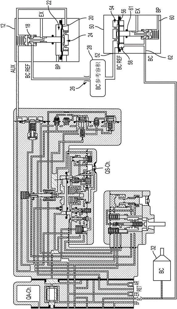
[0014] Referring now to the drawings, in which like reference numerals represent like parts throughout, in figure 1 A schematic illustration of a brake cylinder holding system 10 according to the invention is seen in . The system 10 provides reference pressures for brake cylinder hold in an independent and redundant manner such that the brake cylinder hold reference is not affected by any pre-existing leaks in the brake system, thereby resulting in brake cylinder BC pressure Provides higher pressure regulation accuracy in many different situations of loss.

[0015] The system 10 includes a brake cylinder reference pressure valve 12 that operates in response to the action of a master working piston 14 of a working portion 16 of a railcar braking system, figure 1 A detailed schematic of the working section of a DB-10 commercially available from New York Airlock Co., Watertown, NY is shown in . More specifically, the brake cylinder reference pressure valve 12 has an actuator 18...


PUM


Abstract

A brake cylinder maintaining system produces a brake cylinder reference pressure based on the difference between the brake pipe pressure and the auxiliary reservoir pressure and then feeds that pressure to a choke and a volume so that the ratio of the reference area of the choke to the volume of stored brake cylinder reference pressure is substantively equal to the ratio of a brake cylinder charging valve area to the brake cylinder volume. The resulting reference pressure may be used to adjust brake cylinder pressure by providing the reference pressure to a standard quick service limiting valve or to a relay that can selectively charge or exhaust the brake cylinder.

Description

technical field [0001] The present invention relates to railcar braking systems, and more particularly, to systems for providing accurate brake cylinder reference pressures and improved pressure regulation. Background technique [0002] The fast-working limiting valve of the Association of American Railroads (AAR) type brake system controls the supply of brake pipe air to the brake cylinders during fast-working operation. Recent advances in fast-working limiter valves include modifications to the fast-working limiter valve that help replenish brake cylinder pressure that may be lost, such as through leaks. For example, one approach is to use the brake cylinder reference pressure based on the actual brake cylinder pressure which pressurizes one side of the diaphragm in the fast-working limiting valve so that if the brake cylinder pressure leaks is below the threshold set by the pressure on the opposite side of the diaphragm, the resulting force imbalance will cause a movemen...

Claims


Application Information

Patent Timeline
Patent Type & Authority Applications(China)
IPC IPC(8): B60T15/18
CPCB60T13/665B60T15/022B60T15/185B60T17/228
Inventor 詹森·康奈尔埃里克·C·赖特
Owner NEW YORK AIR BRAKE CORP
Features
  • R&D
  • Intellectual Property
  • Life Sciences
  • Materials
  • Tech Scout
  • Unparalleled Data Quality
  • Higher Quality Content
  • 60% Fewer Hallucinations
Learn More