
Two-input NOT gate type frequency observer
An observer, non-gate technology, applied in the field of teaching instrument demonstration, can solve the problems of inability to popularize teaching instruments, insufficient types of experimental instruments, incomplete experimental instruments, etc., to improve quality education, expand imagination space, and operate light touch. Effect
- Summary
- Abstract
- Description
- Claims
- Application Information
AI Technical Summary
Problems solved by technology
Method used
Image

Examples
Embodiment Construction
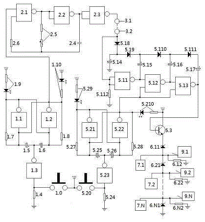
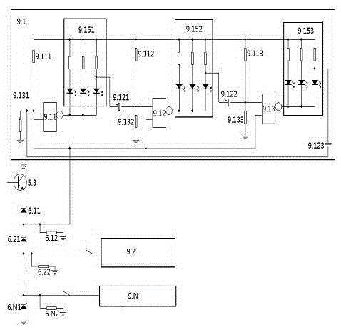
[0105] figure 1 , figure 2 A manner of specific implementation is jointly described.
[0106] 1. Select components: Select the active components according to the diagram, and the pulse resistor is composed of an adjustable resistor connected in series with a fixed resistor. All gates are two-input NAND gates. The emitter follower selects NPN type triode; all diodes are surface-mounted diodes.
[0107] 2. Welding: In addition to the electronic circuits of the display system, press figure 1 connected, displaying the system as figure 2 Welded as shown.
[0108] Three, debugging.
[0109] 1. Check and debug the demonstration power circuit unit.
[0110] Cut off the two-input gate electronic switch unit and the pulse one gate in the demonstration power supply circuit ( figure 1 The connection between 2.1) in the oscilloscope is connected to the isolation gate ( figure 1 2.3) in the output terminal, after power on, the oscilloscope should show oscillation, adjust the puls...
PUM
 Abstract
Description
Claims
Application Information