Rotary type light emitting module and rotary type table lamp

A light-emitting module and rotary technology, applied in electroluminescent light sources, semiconductor devices of light-emitting elements, light sources, etc., can solve the problem that the light-emitting module or table lamp needs to be repaired or replaced, the base and the LED light-emitting module cannot be separated, and the lamp cannot be obtained. efficiency and other issues, to achieve the effects of easy assembly and maintenance, flexible control methods, significant economic and social benefits

Inactive Publication Date: 2017-06-13
吴楚梁
View PDF5 Cites 3 Cited by
  • Summary
  • Abstract
  • Description
  • Claims
  • Application Information

AI Technical Summary

Problems solved by technology

[0002] Existing desk lamps generally adopt an integrated design, and the base and the LED light-emitting module part cannot be separated. If separation is required, the lamp board needs to be removed or the shell needs to be removed. Therefore, once the lamp board fails, the entire light-emitting module will be damaged. Groups or desk lamps need to be repaired or replaced, or even scrapped;
[0003] In addition, the general LED lighting module has only one side of LED light, so it is impossible to obtain different lighting effects (such as warm or cool lighting effects)

Method used


Image

  • Rotary type light emitting module and rotary type table lamp
  • Rotary type light emitting module and rotary type table lamp
  • Rotary type light emitting module and rotary type table lamp

Examples


Embodiment 1

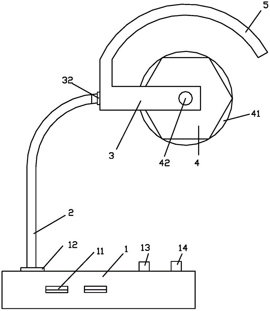
[0076] Embodiment 1: as Figure 1-8 , a rotary light-emitting module, including a prism-shaped light-emitting body 4; both ends of the prism-shaped light-emitting body have rotating shafts 42; at least one arc surface of the rotating shaft is provided with a contact ring 47 for obtaining power or control signals;

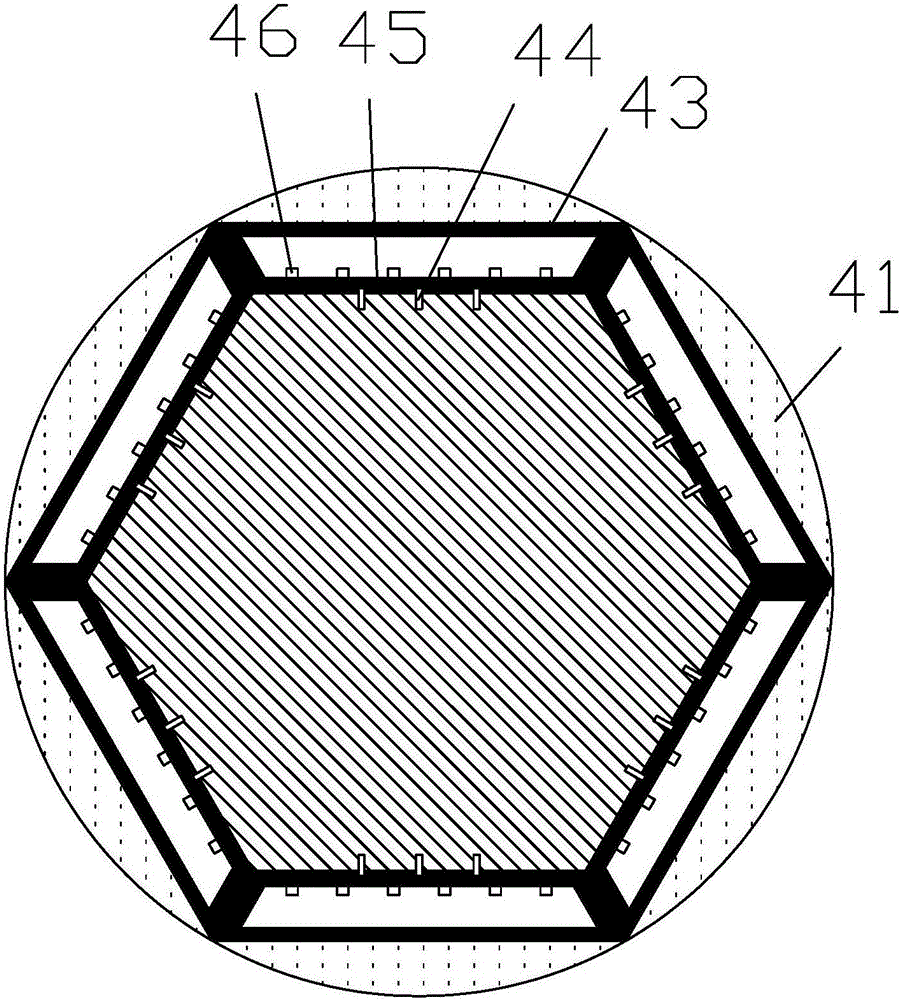
[0077] The prismatic light-emitting body is an N prism; N=6.

[0078] Each side of the prismatic light-emitting body is provided with an LED light board 45;

[0079] The bottom of the LED light board is provided with pins, and each side of the prismatic light-emitting body is provided with a socket adapted to the pins; the sides of the prismatic light-emitting body and the LED light board pass through the pins Electrically connected to the jack;

[0080] The LED lamp board is provided with a plurality of LED lamps 46;

[0081] The upper surface of the LED lamp board is provided with a light-transmitting plate 43; the light-transmitting plate is a light guide plat...


PUM


Abstract

The invention discloses a rotary type light emitting module and a rotary type table lamp. The rotary type light emitting module comprises a prismatic light emitting main body (4), wherein the two ends of the prismatic light emitting main body (4) are both provided with rotating shafts (42), contact rings (47) which are used for obtaining power or control signals are arranged on arc faces of the rotating shafts, the prismatic light emitting main body is an N-prism, the N is an integer and larger than 2, an LED lamp panel (45) is arranged on each lateral side of the prismatic light emitting main body; inserting pins are arranged at the bottoms of the LED lamp panels, inserting holes matched with the inserting pins are formed in all the lateral sides of the prismatic light emitting main body, the lateral sides of the prismatic light emitting main body are electrically connected with the LED lamp panels through the inserting pins and the inserting holes, a plurality of LED lamps (46) are arranged on the LED lamp panels, and light transmitting plates (43) are arranged on the upper surfaces of the LED lamp panels. The table lamp is in a modularized design, and furthermore, the LED light emitting module can rotate, is convenient to switch and easy to assemble and maintain and has good flexibility.

Description

technical field [0001] The invention relates to a rotary light emitting module and a rotary desk lamp. Background technique [0002] Existing desk lamps generally adopt an integrated design, and the base and the LED light-emitting module part cannot be separated. If separation is required, the lamp board needs to be removed or the shell needs to be removed. Therefore, once the lamp board fails, the entire light-emitting module will be damaged. Groups or desk lamps need to be repaired or replaced, or even scrapped; [0003] In addition, the general LED lighting module has only one side of LED light, so it is impossible to obtain different lighting effects (such as warm or cool lighting effects). [0004] Therefore, it is necessary to design a new lighting module and desk lamp. Contents of the invention [0005] The technical problem to be solved by the present invention is to provide a rotary light-emitting module and a rotary table lamp. The rotary light-emitting module ...

Claims


Application Information

Patent Timeline
IPC IPC(8): F21S9/02F21V23/00F21V23/02F21V23/04F21V23/06F21V19/02F21V3/00H05B33/08F21Y115/10F21Y113/17F21Y107/30H05B44/00
CPCF21S6/002F21S9/02F21V3/00F21V19/02F21V23/003F21V23/023F21V23/026F21V23/04F21V23/06H05B45/37Y02B20/30
Inventor 吴楚梁
Owner 吴楚梁
Why Eureka
Try Eureka