Cable low-resistance fault positioning method using single-end and double-end combination

A fault locating and cable technology, applied in the fault location, detecting faults according to conductor types, measuring electricity and other directions, can solve the problems of inaccurate fault locating, aliasing of fault waves, and difficulty in automatic identification, so as to achieve accurate fault locating and avoidance. Wave head aliasing, to achieve the effect of automatic identification

Active Publication Date: 2017-06-13
SOUTH CHINA UNIV OF TECH +1
View PDF4 Cites 6 Cited by
  • Summary
  • Abstract
  • Description
  • Claims
  • Application Information

AI Technical Summary

Problems solved by technology

[0007] Based on this, it is necessary to provide a cable low-resistance fault location method that utilizes a combination of single-end Fault location requires a double-ended data synchronization method that is complex and difficult to implement, and the uncertainty of the wave velocity due to the uncertainty of the cable parameters leads to inaccurate fault location and other issues.

Method used


Image

  • Cable low-resistance fault positioning method using single-end and double-end combination
  • Cable low-resistance fault positioning method using single-end and double-end combination
  • Cable low-resistance fault positioning method using single-end and double-end combination

Examples


Embodiment 1

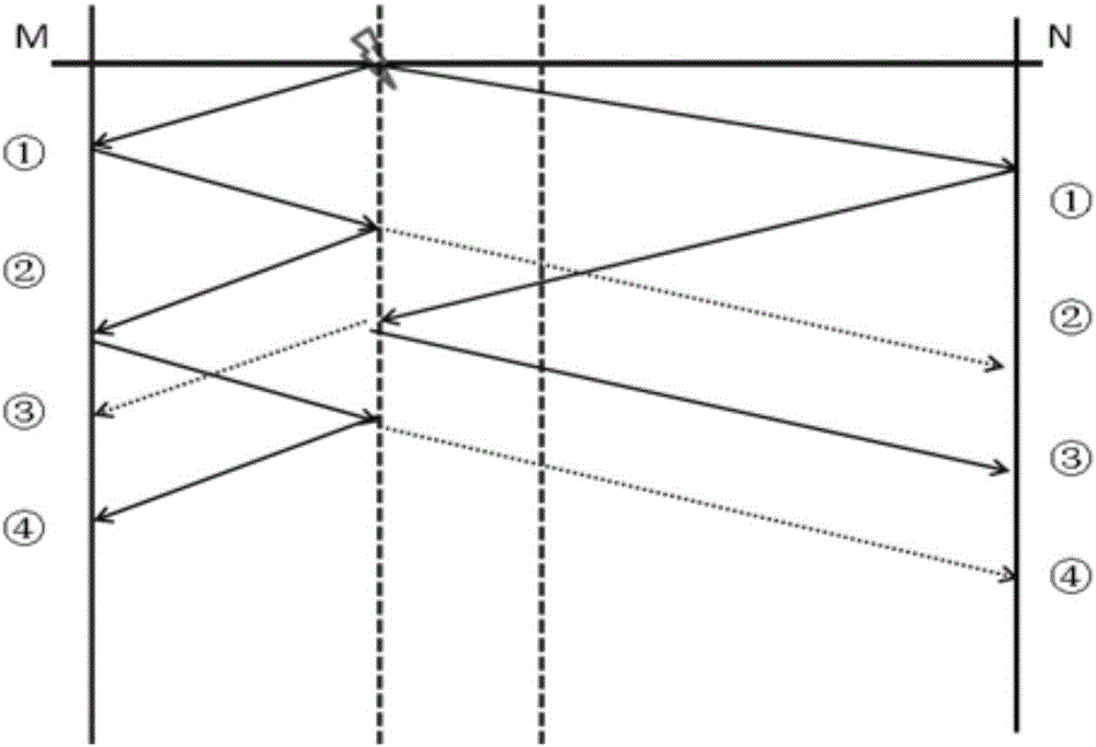
[0077] In Embodiment 1, the times and amplitudes of the four traveling waves first arriving at the M terminal and the N terminal are recorded in Table 1 and Table 2, respectively.

[0078]

[0079] Table 1

[0080] Table 1 is figure 1 The arrival time and modulus maximum value of the M terminal in the time distance diagram shown when the grounding resistance is 10Ω.

[0081]

[0082] Table 2

[0083] Table 2 is figure 1 The arrival time and modulus maximum value of the N terminal in the time distance diagram shown when the grounding resistance is 10Ω.

Embodiment 2

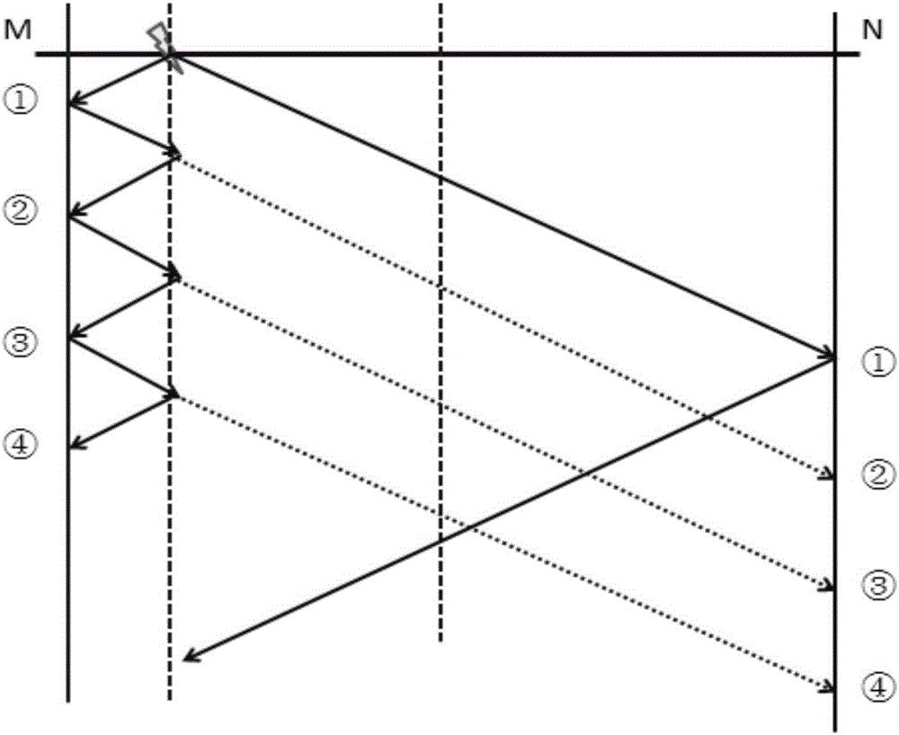
[0084] In the second embodiment, the times and amplitudes of the first four traveling waves arriving at the M terminal and the N terminal are recorded in Table 3 and Table 4, respectively.

[0085]

[0086] table 3

[0087] Table 3 is figure 2 The arrival time and modulus maximum value of the M terminal in the time distance diagram shown when the grounding resistance is 10Ω.

[0088]

[0089] Table 4

[0090] Table 4 is figure 2 The arrival time and modulus maximum value of the N terminal in the time distance diagram shown when the grounding resistance is 10Ω.

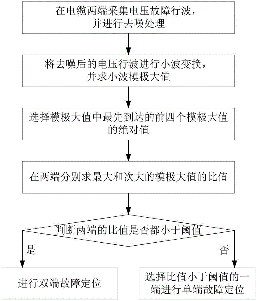
[0091] Step 5. For the near-end and the far-end, respectively select the two with the largest absolute values ​​among the four modulus maxima and record them as:

[0092] A m1 (maximum of near-end modulus maxima), A m2 (the proximal modulus maximum value is the next largest),

[0093] A n1 (maximum value of remote modulus), A n2 (the second largest value of the remote modulus maximum);

[0094] Find t...

Embodiment 2

[0097] For the second embodiment, the M terminal is 4763 / 2241=2.1254>5, so the second embodiment uses the single-ended method for fault location.

[0098] In the above step 5, if the ratios of the near-end and the far-end are both less than or equal to the threshold, then the two modulus maxima correspond to the arrival times of the initial fault wave and the reflected wave at the fault point required by the corresponding end.

[0099] In Embodiment 1, the ratios of the modulus maxima at the M-terminal and the N-terminal are both smaller than the threshold, the sampling points corresponding to the two modulus maxima at the M-terminal are 2077 and 2232, and the sampling points corresponding to the two modulus maxima at the N-terminal The sampling points are 2123 and 2370. According to the sampling interval, the time difference between the fault initial wave and the first fault reflection wave can be obtained.

[0100] In the above step 5, if the ratio between the near end and ...


PUM


Abstract

A cable low-resistance fault positioning method using single-end and double-end combination includes the steps that fault traveling waves are collected at the two ends of a cable respectively; denoising processing is conducted to obtain a denoised signal; wavelet transformation is conducted, and modulus maximas are solved; first Y modulus maximas at each end are obtained; an absolute value maximum value and an absolute value secondary maximum value in the first Y modulus maximas at each end are selected; the ratio of the absolute value maximum value to the absolute value secondary maximum value at each end is obtained; whether the two ratios are smaller than or equal to a preset threshold is judged; if the two judgment results are both positive, two-end fault positioning is conducted; if any of the two judgment result is negative, single-end fault positioning is conducted on the end where the smaller ratio in the two ratios is located. By means of the method, two-end fault positioning and single-end fault positioning can be flexibly used according to conditions by means of fault positioning and classifying of the two ends, and the method has the technical advantage that fault positioning is accurate.

Description

technical field [0001] The invention relates to the field of fault detection in power systems, in particular to a cable low-resistance fault location method utilizing single-double-end combination. Background technique [0002] Economic development is inseparable from the supply of electricity, and with the increase of electricity supply, the length of cables is also increasing. However, in the distribution network, cables are generally buried underground. If there is no fault distance measurement, once a fault occurs, it will Greatly increase the workload of manual line inspection. Therefore, fault location plays a very important role in today's power transmission and distribution systems. [0003] At present, the mainstream cable fault location methods at home and abroad are impedance method and traveling wave method. Impedance method is more accurate in positioning when there are accurate line parameters. However, due to various factors in practical applications, it is ...

Claims


Application Information

Patent Timeline
Patent Type & Authority Applications(China)
IPC IPC(8): G01R31/08
CPCG01R31/083G01R31/088
Inventor 李波田立斌尤予展刘鑫李汉豪
Owner SOUTH CHINA UNIV OF TECH
Why Eureka
Try Eureka