Backlight module and display device

A backlight module and backplane technology, applied in light guides, optics, optical components, etc., can solve problems such as luminance, poor light uniformity, unfixed distance between the light source and the light guide plate, and unstable optical quality of the backlight module. Achieve the effect of improving the display effect, improving the uniformity of the picture, and facilitating assembly

Active Publication Date: 2019-03-15
BOE OPTICAL SCI & TECH +1
View PDF5 Cites 0 Cited by
  • Summary
  • Abstract
  • Description
  • Claims
  • Application Information

AI Technical Summary

Problems solved by technology

In the existing side-entry backlight modules, the combination between the light source and the light guide plate is mainly divided into two forms: one is in medium and large backlight modules such as vehicles, industrial control, and notebooks, the combination between the light source and the light guide plate There is a design gap between the light source and the light guide plate, which causes the distance between the light source and the light guide plate to be unstable or the light guide plate is in a movable state in the backlight module, resulting in unstable optical quality of the backlight module and prone to poor luminance and light uniformity; One is that in small and medium-sized backlight modules such as mobile phones and feature phones, the light source and the light guide plate are pasted through a flexible circuit board. There are gaps between the light guide plates, which will also cause the above-mentioned defects such as luminance and light uniformity.

Method used


Image

  • Backlight module and display device
  • Backlight module and display device
  • Backlight module and display device

Examples


Embodiment Construction

[0026] Specific embodiments of the present invention will be described in detail below in conjunction with the accompanying drawings. It should be understood that the specific embodiments described here are only used to illustrate and explain the present invention, and are not intended to limit the present invention.

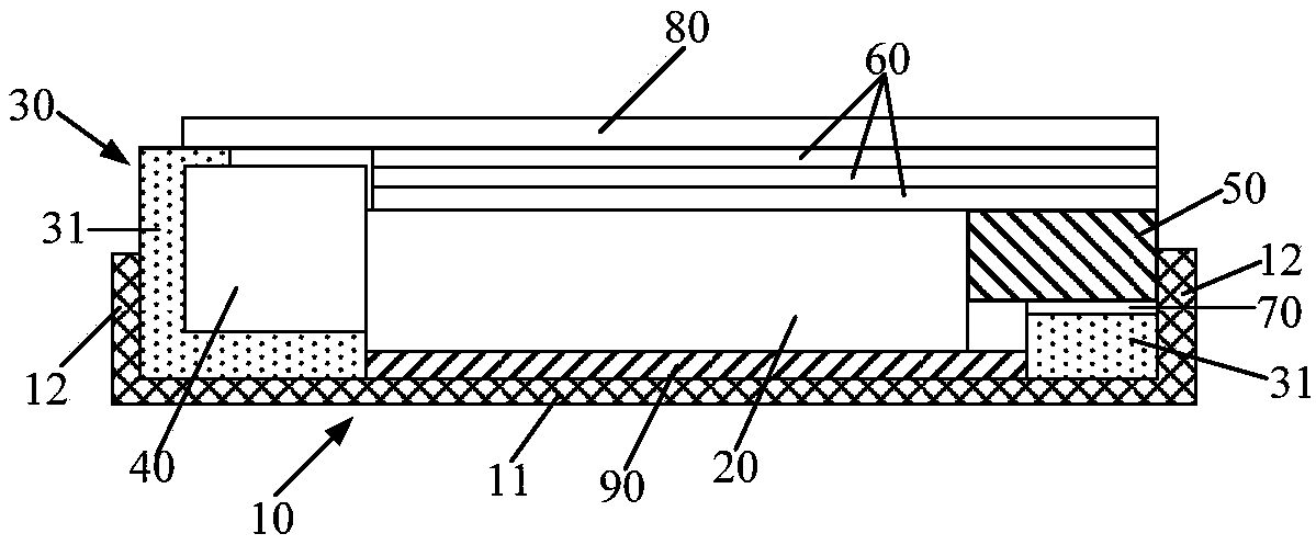
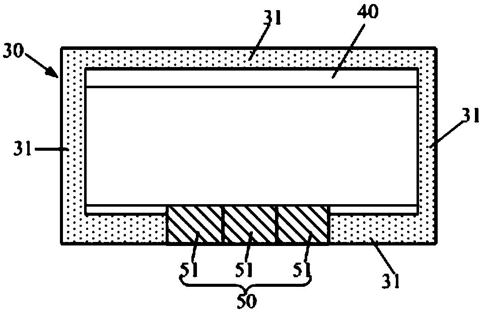
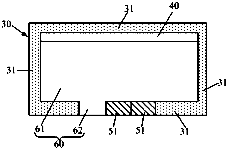
[0027] As an aspect of the present invention, a backlight module is provided, such as figure 1 As shown, the backlight module includes a backplane 10, a light guide plate 20 and a plastic frame 30, the plastic frame 30 includes a plurality of plastic frame walls 31 arranged around the light guide plate 20, the backplane 10 includes a bottom wall 11 and a plastic frame 30 arranged around A plurality of side walls 12, wherein a light source 40 is provided between a plastic frame wall 31 and the light guide plate 20, and a mounting block 50 is also provided between the side wall of the back plate 10 away from the light source 40 and the light guide plate 20, the mo...


PUM


Abstract

The invention provides a backlight module which comprises a backboard, a light guide board and a rubber frame. The rubber frame comprises a plurality of rubber frame walls arranged around the light guide board, the backboard comprises a bottom wall and a plurality of side walls arranged around the rubber frame, and a light source is arranged between one rubber frame wall and the light guide board. A mounting block is arranged between the side wall, away from the light source, of the backboard and the light guide board, and the side face, towards the light guide board, of the mounting block protrudes out of the side, towards the light guide board, of the corresponding rubber frame wall so that the light guide board can be clamped between the light source and the mounting block. Correspondingly, the invention provides a display device. The relative stability of the light guide board and a light bar can be guaranteed, and the optical quality of the backlight module can be improved.

Description

technical field [0001] The invention relates to the field of display technology, in particular to a backlight module and a display device. Background technique [0002] The side-type backlight module is provided with a light guide plate, and the light source is installed on one side of the light guide plate to emit light into the light guide plate, and the light guide plate diffuses the light and is installed from the top surface to form a surface light source and provide it to the display panel. In the existing side-entry backlight modules, the combination between the light source and the light guide plate is mainly divided into two forms: one is in medium and large backlight modules such as vehicles, industrial control, and notebooks, the combination between the light source and the light guide plate There is a design gap between the light source and the light guide plate, which causes the distance between the light source and the light guide plate to be unstable or the li...

Claims


Application Information

Patent Timeline
Patent Type & Authority Patents(China)
IPC IPC(8): G02B6/00
CPCG02B6/0086G02B6/0088
Inventor 王文德
Owner BOE OPTICAL SCI & TECH
Why Eureka
Try Eureka