Backlight module and liquid-crystal display device

A backlight module and backplane technology, applied in optics, nonlinear optics, television, etc., can solve problems such as crowded lights, complicated design and printing process, color cast, etc.

Inactive Publication Date: 2017-06-13
HISENSE VISUAL TECH CO LTD
View PDF6 Cites 4 Cited by
  • Summary
  • Abstract
  • Description
  • Claims
  • Application Information

AI Technical Summary

Problems solved by technology

[0002] Existing backlight modules can be divided into direct-type and side-type backlight modules. In side-type backlight modules, since the LED light source is located at the edge of the backlight module, it is necessary to add a light guide plate so that part of the light path is in the light guide plate. Total reflection occurs on the surface, and at the same time, dots are set on the lower surface of the light guide plate to control the reflection angle of the light path, and then convert the point/line light source on the side into a uniform surface light source; however, adding a light guide plate also makes the process of side-type backlight modules more difficult. Big
First of all, because the light guide plate is significantly affected by temperature, the optical structure processing of the light incident surface is very complicated; secondly, the lower surface of the light guide plate needs to be provided with dots for changing the reflection

Method used


Image

  • Backlight module and liquid-crystal display device
  • Backlight module and liquid-crystal display device
  • Backlight module and liquid-crystal display device

Examples


Embodiment 1

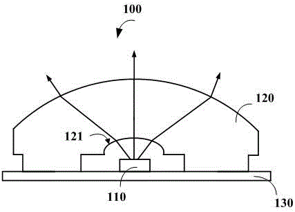
[0034] In the existing direct type backlight module, the structure of the optical device is as follows figure 1 As shown, the optical device 100 includes an LED light source 110 , an optical lens 120 and a PCB board 130 , wherein the LED light source 110 is disposed on the PCB board for providing a backlight source, and the optical lens 120 is fixedly connected to the PCB board 130 . Wherein, the optical lens 120 is used to diffuse the light path emitted by the LED light source, so that the backlight provided by the LED light source is emitted at a larger angle, and the emission range of the light path of the backlight is increased, so that it can emit from the display area more uniformly.

[0035] Obviously, if the optical devices of the existing direct-type backlight module are directly used in the side-type backlight module without a light guide plate, most of the light path will still exit from the near-beam side of the light source, and the side point / Line lights are con...

Embodiment 2

[0064] Embodiment 2 of the present application further provides a liquid crystal display device, comprising a liquid crystal panel and the backlight module described in Embodiment 1 above. Wherein, the backlight module and the liquid crystal panel are at opposite positions, and the liquid crystal panel is located on the upper surface of the backlight module; the structure, function and function of the backlight module have been described in detail in the foregoing embodiment 1, and will not be repeated here.


PUM


Abstract

The invention provides a backlight module and a liquid-crystal display device. A light-emitting device can be applied to a lateral-entrance backlight module without a light guide plate. The backlight module comprises an LED (Light-Emitting Diode) light source for providing backlight and an optical lens for aligning and emitting LED backlight within a certain angle. The optical lens comprises a bottom surface, a cambered surface opposite to the bottom surface, a vertical surface which is positioned on the two sides of the cambered surface and is connected with the connected with the cambered surface, and a slope which is connected with the bottom surface and the vertical surface, wherein the cambered surface, the vertical surface and the slope are all used for emitting the backlight provided by the LED light source. By adopting the novel optical device provided by the application, most backlight which is originally emitted from the near light side of the LED light source can reach the distance light side of the LED light source after being aligned at a certain degree and is emitted from one end of the distance light side, so that uniform light emitting in a display area is realized.

Description

technical field [0001] The invention relates to the field of liquid crystal television backlights, in particular to a backlight module and a liquid crystal display device. Background technique [0002] Existing backlight modules can be divided into direct-type and side-type backlight modules. In side-type backlight modules, since the LED light source is located at the edge of the backlight module, it is necessary to add a light guide plate so that part of the light path is in the light guide plate. Total reflection occurs on the surface, and at the same time, dots are set on the lower surface of the light guide plate to control the reflection angle of the light path, and then convert the point / line light source on the side into a uniform surface light source; however, adding a light guide plate also makes the process of side-type backlight modules more difficult. big. First of all, because the light guide plate is significantly affected by temperature, the optical structure...

Claims


Application Information

Patent Timeline
IPC IPC(8): H04N5/64G02F1/1335
CPCH04N5/64G02F1/133615
Inventor 文喜平张登印宋志成张大鹏
Owner HISENSE VISUAL TECH CO LTD
Why Eureka
Try Eureka