Lens and light source module with same

A technology of lens and light incident surface, which is applied in the field of optics, can solve the problems of reducing the lighting efficiency of light sources, and achieve the effect of improving utilization efficiency and strengthening lighting

Inactive Publication Date: 2015-03-25
HONG FU JIN PRECISION IND (SHENZHEN) CO LTD +1
View PDF5 Cites 7 Cited by
  • Summary
  • Abstract
  • Description
  • Claims
  • Application Information

AI Technical Summary

Problems solved by technology

This part of light enters the lens at a relatively large angle, diverges after being refracted by the lens, and sometimes exits in the opposite direction to the front of the light source. In this way, this part of light cannot be actually used to bring lighting effects, thereby reducing the light source. lighting efficiency

Method used


Image

  • Lens and light source module with same
  • Lens and light source module with same
  • Lens and light source module with same

Examples


Embodiment Construction

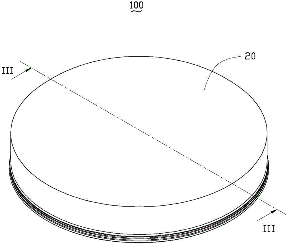
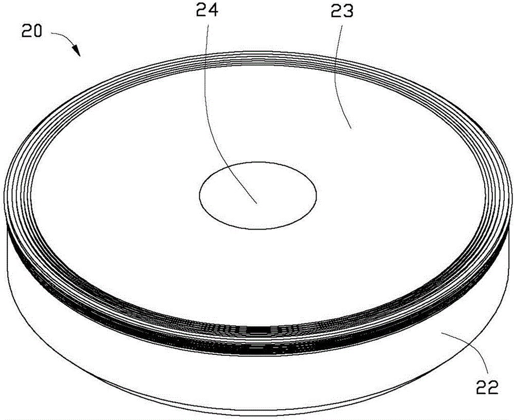
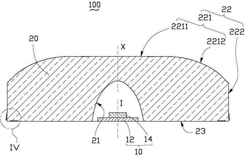
[0015] see Figure 1 to Figure 3 A light source module 100 provided by an embodiment of the present invention includes a light source 10 and a lens 20 disposed on the light source 10 . The lens 20 includes a light incident surface 21 opposite to the light source 10 , a light exit surface 22 opposite to the light incident surface 21 , and a connecting surface 23 connecting the light incident surface 21 and the light exit surface 22 . The light source 10 has an optical axis I. The light emitted by the light source 10 is roughly distributed within a spatial angle of 180 degrees relative to the optical axis I, and most of the light is concentrated and distributed within a spatial angle of 120 degrees relative to the optical axis I.

[0016] In this embodiment, the light source 10 is a light emitting diode, including a base 12 and a light emitting diode chip 14 fixed on the base 12 . The base 12 is made of insulating materials such as epoxy resin, silica gel or ceramics. The lig...


PUM


Abstract

A light source module comprises a light source and a lens right facing the light source. The lens comprises a light entering face right facing the light source, a light emitting face opposite to the light entering face and a connecting face connected with the light entering face and the light emitting face, the connecting face is an annular plane surrounding the light entering face, the light emitting face is in butt joint with the peripheral edge of the connecting face, the lens further comprises a plurality of first annular protrusions protruding and extending out of the light emitting face outwards, and the first protrusions are arranged nearby the connecting face. The emitting direction is changed after light emitted out of the light source relative to the optical axis of the light source by a large angle is refracted or totally reflected on the first protrusions of the lens, the emitting angle of at least part of the light relative to the optical axis is reduced, and therefore illumination of the light source module can be enhanced. Compared with the prior art, the light source module achieves the effect of improving the utilization efficiency of the light emitted by the light source.

Description

technical field [0001] The invention relates to the field of optics, in particular to a lens and a light source module using the lens. Background technique [0002] At present, in backlighting, in order to uniform the light, a diffuser lens is usually used on the light source, so that the light emitted by the light source can exit at a larger angle, thereby achieving the effect of large-area lighting. [0003] In actual use, the light emitted by the light source is roughly distributed within a space angle of 180 degrees relative to the optical axis of the light source, and most of the light is concentrated and distributed within a space angle of 120 degrees relative to the optical axis, that is, roughly toward the direction of the light source. Shooting in the front direction. However, some light rays still enter the lens at relatively large angles to the optical axis of the light source, such as between 120° and 180°. This part of light enters the lens at a relatively lar...

Claims


Application Information

Patent Timeline
IPC IPC(8): F21V5/04
CPCF21V5/04F21K9/60F21Y2101/00
Inventor 王何立颖
Owner HONG FU JIN PRECISION IND (SHENZHEN) CO LTD
Why Eureka
Try Eureka