Tunnel entrance and exit sunlight directional reflection direct illumination device and method

A technology of directional reflection and sunlight, applied in the field of solar energy utilization, can solve the problems of increasing system cost, high system failure rate, restricting cost performance, etc., to achieve the effect of strengthening lighting

Pending Publication Date: 2021-07-27
SHAANXI UNIV OF SCI & TECH
View PDF4 Cites 0 Cited by
  • Summary
  • Abstract
  • Description
  • Claims
  • Application Information

AI Technical Summary

Problems solved by technology

[0003] At present, conventional power is mostly used in tunnel enhanced lighting, and high-pressure sodium lamps, LED lights, etc. are used as lighting sources. The practical problem of high failure rate forces people to give up the automatic control function to ensure the reliability of the system. Usually, the enhanced lighting system is a constant lighting system designed and equipped according to the strongest sunlight in summer, and works in the same state as the basic lighting system. High reliability ensures that the requirements are met, but at the same time it causes a huge waste of electrical energy
In the related technology, the optical fiber sunlight conveyor is used to introduce the sunlight outside the tunnel into the tunnel to enhance the lighting, and realize the enhanced lighting function of directly using the sunlight at the entrance and exit of the tunnel. Not only does it increase the system cost, but the long-distance transmission efficiency is only about 30%, which also restricts the improvement of cost performance

Method used


Image

  • Tunnel entrance and exit sunlight directional reflection direct illumination device and method
  • Tunnel entrance and exit sunlight directional reflection direct illumination device and method
  • Tunnel entrance and exit sunlight directional reflection direct illumination device and method

Examples


Embodiment Construction

[0024] The present invention will be further explained below in conjunction with the accompanying drawings and specific embodiments. Apparently, the described embodiments are part of the embodiments of the present application, not all of them. Based on the embodiments in this application, all other embodiments obtained by persons of ordinary skill in the art without making creative efforts belong to the scope of protection of this application.

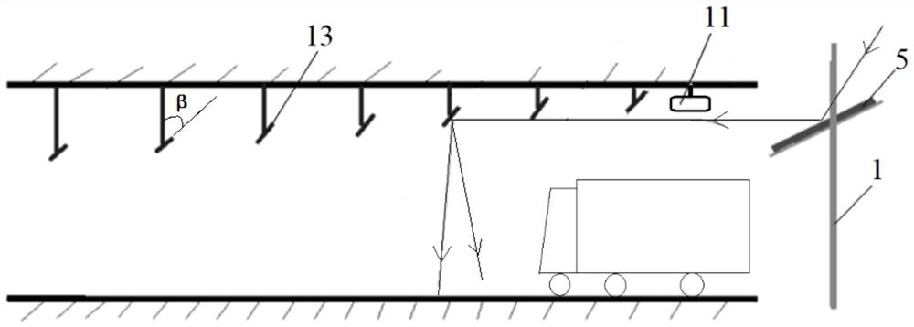
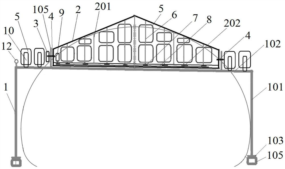
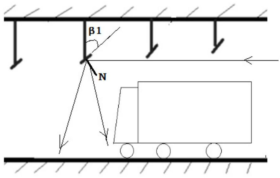
[0025]The embodiment of the present invention provides a device for directional reflection and direct illumination of sunlight at the entrance and exit of a tunnel, see Figure 1 to Figure 7b , the device of the present invention includes a plurality of diffuse mirrors 13 arranged at intervals from outside to inside at the top of the tunnel mouth, and the installation heights of the multiple diffuse mirrors 13 are successively decreased from outside to inside, and the quasi-plane of the diffuse mirror 13 is according to the vehicle driv...


PUM


Abstract

The invention discloses a tunnel entrance and exit sunlight directional reflection direct illumination device and method, which can efficiently utilize sunlight to intensify illumination in the tunnel entrance and exit, reduce the brightness gradient of the tunnel entrance and exit, improve the vehicle driving safety, save energy and protect an environment. The device comprises a plurality of diffuse reflectors which are sequentially arranged at the top of a tunnel portal at intervals from outside to inside, the installation heights of the diffuse reflectors are sequentially decreased from outside to inside, and the collimation planes and the vertical lines of the diffuse reflectors are arranged at different angles according to the vehicle driving direction; a supporting frame is fixedly arranged on the outer side of the tunnel portal, and a rotating frame is rotatably arranged at the top of the supporting frame. the rotating frame is in transmission connection with a first driving mechanism, a plurality of directional mirror reflectors capable of directionally reflecting sunlight to the diffuse reflectors are rotatably arranged on the rotating frame, and the directional mirror reflectors are all in transmission connection with a second driving mechanism; and the top of the inner side of the tunnel portal is provided with a light direction sensor located on the path of sunlight reflected by the directional reflector. And a controller is included.

Description

technical field [0001] The invention relates to the technical field of solar energy utilization, in particular to a device and method for directional reflection and direct illumination of sunlight at an entrance and exit of a tunnel. Background technique [0002] With the rapid development of the country's economy, the transportation industry marked by expressways has developed rapidly. However, the operation and management costs of highway tunnels, especially the electricity costs for tunnel lighting, have become a huge expenditure, and the contradiction between safety and energy conservation has become increasingly prominent. For the driver, the brightness gradient at the entrance and exit section of the tunnel is too large at a certain speed of the car, which will cause the vision to be unable to adjust as soon as possible, resulting in "black hole" and "white hole" effects, which will increase the probability of traffic accidents. In order to ensure energy saving under t...

Claims


Application Information

Patent Timeline
IPC IPC(8): F21S11/00F21V7/00F21V17/08F21V7/24F21V7/28F21V14/04F21W131/101
CPCF21S11/005F21S11/007F21V7/0025F21V17/08F21V7/24F21V7/28F21V14/04F21W2131/101
Inventor 宁铎赵超志亢洁韩常领毛金沙董长松孟惠刘嫣李宏杰任西伟
Owner SHAANXI UNIV OF SCI & TECH
Why Eureka
Try Eureka