Photoelectric sensor and electronic equipment

A technology for photoelectric sensors and electronic equipment, applied in the field of sensors, can solve the problems of incorrect ambient light brightness, failure of light incident to the photoelectric sensor, and large influence of the photoelectric sensor, etc., to achieve the effect of ensuring accuracy

Active Publication Date: 2019-01-11
BEIJING XIAOMI MOBILE SOFTWARE CO LTD
View PDF4 Cites 0 Cited by
  • Summary
  • Abstract
  • Description
  • Claims
  • Application Information

AI Technical Summary

Problems solved by technology

[0004] However, this way of setting the through hole, because the through hole restricts that only light with a specific incident angle can pass through the through hole, the light received by the photoelectric sensor is greatly affected by the incident angle of the light
E.g Figure 1A As shown, when the user holds the electronic device in a certain posture, the light can be incident on the photoelectric sensor in the electronic device, and when the user slightly changes the posture of the electronic device, for example Figure 1B As shown, although ambient light can pass through the hole, the light is not incident on the photosensor in the electronic device
[0005] This leads to a large change in the light received by the photoelectric sensor due to the change in the attitude of the electronic device where the photoelectric sensor is located when the brightness of the ambient light has not changed, resulting in a wrong judgment on the brightness of the ambient light

Method used


Image

  • Photoelectric sensor and electronic equipment
  • Photoelectric sensor and electronic equipment
  • Photoelectric sensor and electronic equipment

Examples


Embodiment Construction

[0041] Reference will now be made in detail to the exemplary embodiments, examples of which are illustrated in the accompanying drawings. When the following description refers to the accompanying drawings, the same numerals in different drawings refer to the same or similar elements unless otherwise indicated. The implementations described in the following exemplary examples do not represent all implementations consistent with the present disclosure. Rather, they are merely examples of apparatuses and methods consistent with aspects of the present disclosure as recited in the appended claims.

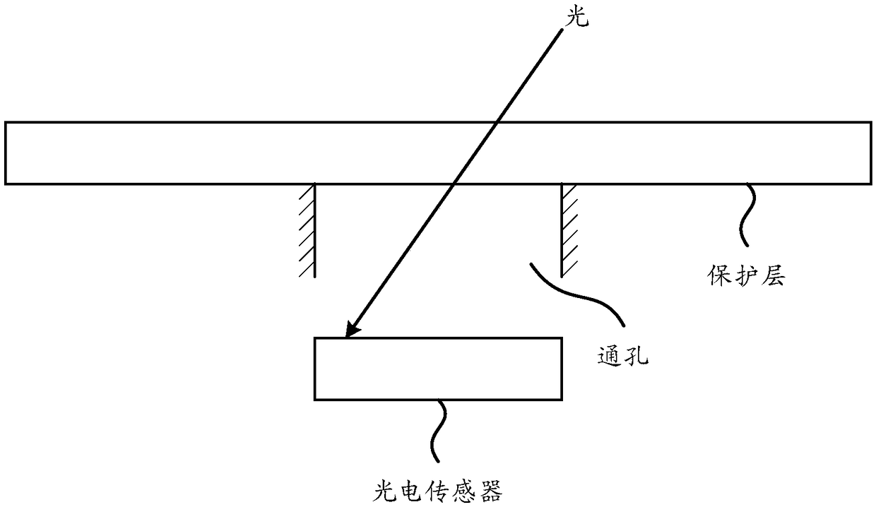
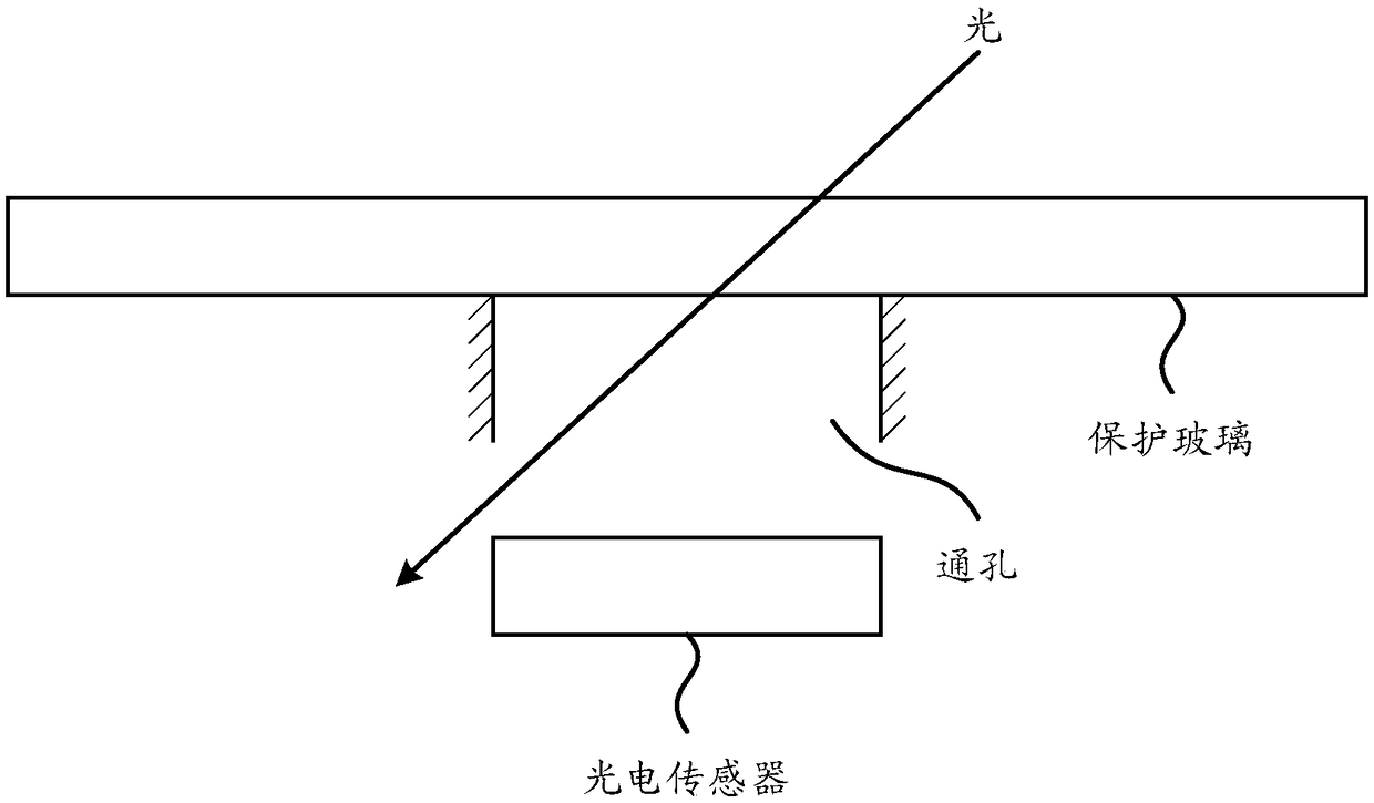
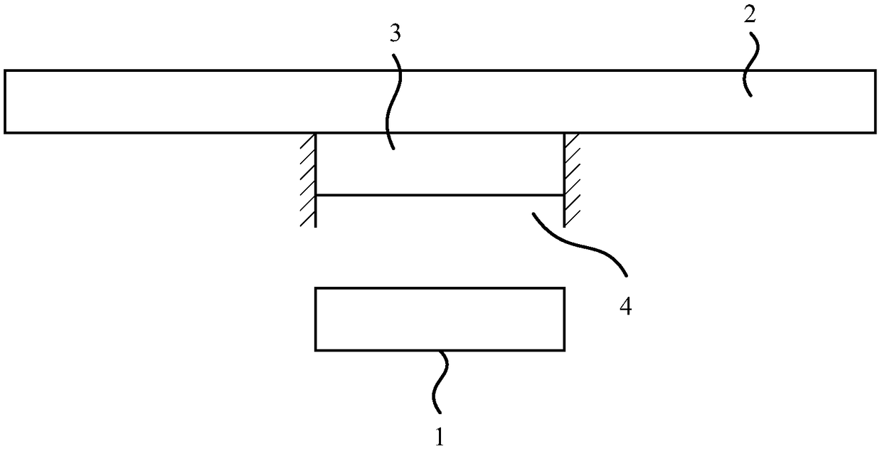
[0042] figure 2 It is a schematic structure diagram of a photoelectric sensor shown according to an embodiment of the present disclosure. The photoelectric sensor shown in this embodiment can be applied to electronic equipment, such as mobile phones, tablet computers, etc., the electronic equipment includes a display panel and a protective layer, and the electronic equipment can perf...


PUM


Abstract

The invention relates to a photoelectric sensor which is applied to electronic equipment. The electronic equipment comprises a display panel and a protective layer. The photoelectric sensor includes alight sensation array and a diffuser, wherein the light sensation array is arranged on the side, close to the display panel, of the protective layer, and the diffuser is arranged between the light sensation array and the protective layer and is used for changing the propagation direction of light rays emitting into the electronic equipment from the protective layer. According to the embodiment ofthe photoelectric sensor and the electronic equipment, the diffuser is arranged between the light sensation array and the protective layer, after the light rays emit into the diffuser, the propagation direction after emitting out of the diffuser decreases due to the optical diffusion effect of a diffusion layer, the light rays with large incident angle can also be received by the light sensationarray, thus under the condition that the ambient radiance does not change, even if the incident ray angle changes, the light intensity sensed by the light sensation array also cannot change much, andthen the accuracy of induction results of the photoelectric sensor is ensured.

Description

technical field [0001] The present disclosure relates to the field of sensor technology, in particular to photoelectric sensors and electronic equipment. Background technique [0002] Full screen has become the development trend of electronic equipment. However, the current screen of electronic equipment is not a full screen in the true sense. Due to the existence of the front camera and various sensors, it is inevitable to occupy the area on one side of the screen, resulting in screen distortion. proportion decreased. [0003] Wherein, in order to reduce the area occupied by the photoelectric sensor, in the related art, a through hole is generally provided on one side of the screen, and then the photoelectric sensor is arranged under the through hole. [0004] However, in this way of setting the through hole, because the through hole restricts that only light with a specific incident angle can pass through the through hole, the light received by the photoelectric sensor is...

Claims


Application Information

Patent Timeline
IPC IPC(8): G01J1/42G02B5/02
CPCG01J1/4204G02B5/02
Inventor 陈朝喜
Owner BEIJING XIAOMI MOBILE SOFTWARE CO LTD
Why Eureka
Try Eureka