Automatic calibration algorithm for multi-group multi-line laser radar
A laser radar, multi-line laser technology, applied in radio wave measurement systems, instruments, etc., can solve the problems of difficult radar to find target points, complicated operation, etc.
- Summary
- Abstract
- Description
- Claims
- Application Information
AI Technical Summary
Problems solved by technology
Method used
Image
Examples
Embodiment 1
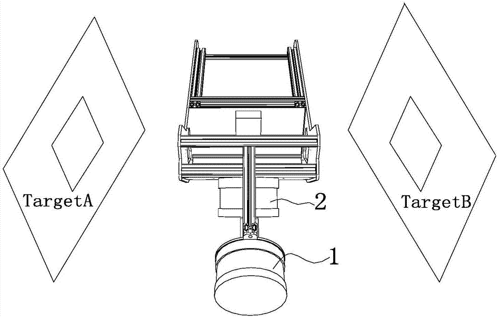
[0035] Calibration of lidar A and lidar B is performed manually. Such as image 3 As shown, the common viewpoint manual registration method is used to place the square hole target in the radar common vision area. Since the radar common vision area is small, in order to ensure the density of target sampling points, we set the size of the target hole to 200x200mm, and set the target A Place them and B on the left and right sides of the system about one meter apart. Such as Figure 4 As shown, two sets of point clouds are obtained.
[0036] Depend on Figure 4 It can be seen that the point cloud of the multi-line radar is very sparse, and it is difficult to find the corresponding points in the square hole targets of the two sets of point clouds, so we use RANSAC fitting (RANSAC fitting belongs to the existing technology, so I won’t repeat it here. ) method, from which two squares are fitted, and the corresponding points are found on the corners of the squares for coordinate t...
Embodiment 2
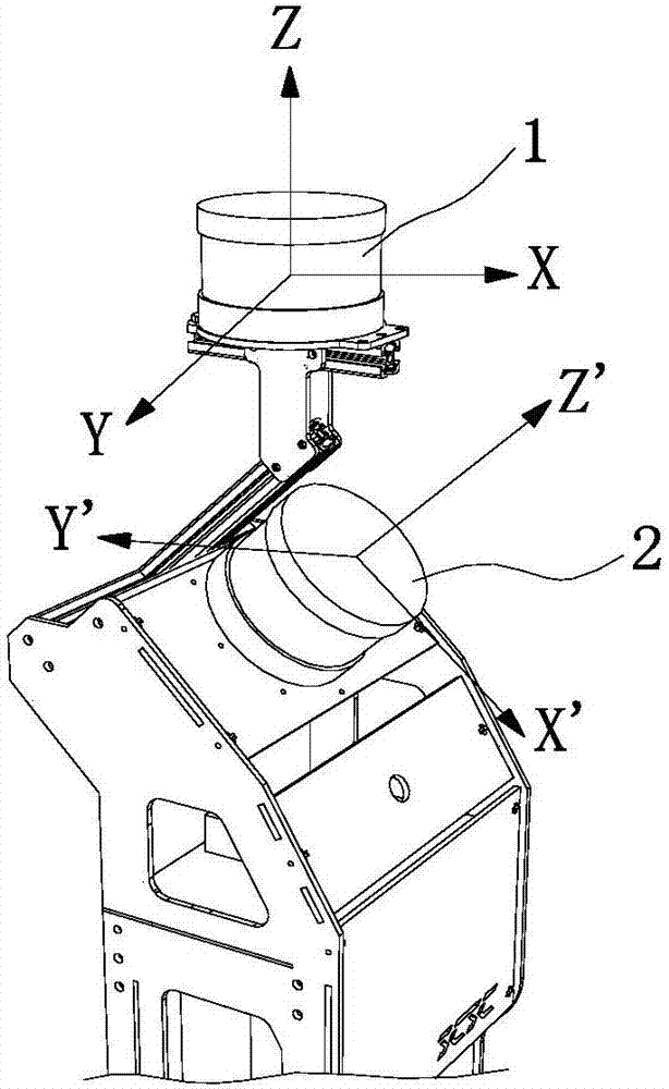
[0043] Using multi-group multi-line laser radar automatic calibration algorithm figure 1 The two-line radar 3D scanning system shown is automatically calibrated.
[0044] Place the system in any structured scene for data collection. This embodiment uses the corridor environment and two sets of scenes. Each set of scenes is walked once, and there are 2 sets of data in total, and each set of data collects 550 frames of point cloud data. Such as Figure 5 As shown, the point cloud data collected by radar A is constructed using the map construction algorithm in a short period of time to obtain a submap M. The data of radar B is transformed to the corresponding position of the map of radar A after initial value rotation and synchronous pose. Then perform automatic calibration and correction.
[0045] Specific steps such as Figure 6 Shown:
[0046] S1. Based on the positional relationship between Lidar A and Lidar B, estimate the initial value T of the coordinate transformatio...
PUM
 Abstract
Description
Claims
Application Information
 - R&D
- Intellectual Property
- Life Sciences
- Materials
- Tech Scout
- Unparalleled Data Quality
- Higher Quality Content
- 60% Fewer Hallucinations
Browse by: Latest US Patents, China's latest patents, Technical Efficacy Thesaurus, Application Domain, Technology Topic, Popular Technical Reports.
© 2025 PatSnap. All rights reserved.Legal|Privacy policy|Modern Slavery Act Transparency Statement|Sitemap|About US| Contact US: help@patsnap.com


