
An automatic calibration algorithm for multi-group multi-line laser radar

A laser radar, multi-line laser technology, applied in radio wave measurement systems, instruments, etc., can solve the problems of difficult radar to find target points, complicated operation, etc.

Active Publication Date: 2019-08-27
XIAMEN UNIV
View PDF7 Cites 2 Cited by
  • Summary
  • Abstract
  • Description
  • Claims
  • Application Information

AI Technical Summary

Problems solved by technology

The target calibration method improves the calibration accuracy to a certain extent, but it requires a special target with specific geometric features, and the operation is more complicated. Find the exact corresponding target point in

Method used


Image

  • An automatic calibration algorithm for multi-group multi-line laser radar
  • An automatic calibration algorithm for multi-group multi-line laser radar
  • An automatic calibration algorithm for multi-group multi-line laser radar

Examples


Embodiment 1

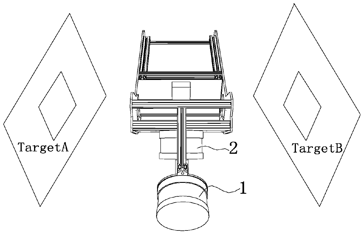
[0036] Calibration of lidar A and lidar B is performed manually. Such as image 3 As shown, the common viewpoint manual registration method is used to place the square hole target in the radar common vision area. Since the radar common vision area is small, in order to ensure the density of target sampling points, we set the size of the target hole to 200x200mm, and set the target A Place them and B on the left and right sides of the system about one meter apart. Such as Figure 4 As shown, two sets of point clouds are obtained.

[0037] Depend on Figure 4 It can be seen that the point cloud of the multi-line radar is very sparse, and it is difficult to find the corresponding points in the square hole targets of the two sets of point clouds, so we use RANSAC fitting (RANSAC fitting belongs to the existing technology, so I won’t repeat it here. ) method, from which two squares are fitted, and the corresponding points are found on the corners of the squares for coordinate t...

Embodiment 2

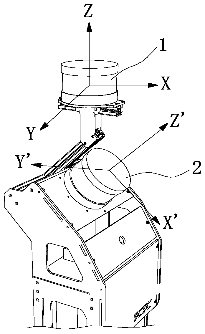
[0044] Using multi-group multi-line laser radar automatic calibration algorithm figure 1 The two-line radar 3D scanning system shown is automatically calibrated.

[0045] Place the system in any structured scene for data collection. This embodiment uses the corridor environment and two sets of scenes. Each set of scenes is walked once, and there are 2 sets of data in total, and each set of data collects 550 frames of point cloud data. Such as Figure 5 As shown, the point cloud data collected by radar A is constructed using the map construction algorithm in a short time to obtain a submap M. The data of radar B is transformed to the corresponding position of the map of radar A after initial value rotation and synchronous pose. Then perform automatic calibration and correction.

[0046] Specific steps such as Figure 6 Shown:

[0047] S1. Based on the positional relationship between Lidar A and Lidar B, estimate the initial value T of the coordinate transformation relation...


PUM


Abstract

The invention discloses an automatic calibration algorithm for a multi-group multi-line laser radar. The automatic calibration algorithm is implemented as follows: S1, a coordinate transformation relation initial value Tguess of a laser radar A and a laser B is estimated; S2, local sub map M construction is carried out on point cloud data collected by the laser radar A; S3, on the basis of hypotheses of data synchronization and track synchronization, the point data P<n>B are transformed to positions at the local sub map M at a time n by T<n>A and the Tguess and a near point at the local sub map M is found out by using a nearest neighbor point cloud searching algorithm; S4, on the basis of an environment consistency constraint, a multi-group calibration relation T<n>cali; between the laser radar A and the laser radar B is calculated; and S5, an abnormal sample point in a multi-group calibration matrix is eliminated by using a random sampling consistency rule and then averaging is carried out to obtain Tcali. According to the automatic calibration algorithm, a coordinate relationship between radars can be calibrated automatically only according to synchronization radar of the laser radar sensor, so that the operation becomes efficient and convenient; and the automatic calibration algorithm can be applied to calibration of a multi-radar system.

Description

technical field [0001] The invention relates to an automatic calibration algorithm for multi-group multi-line laser radar. Background technique [0002] In 3D reconstruction and SLAM applications based on multi-line lidar scanning, multi-sensor data fusion can often bring better robustness and accuracy to the algorithm, and at the same time capture more 3D details of the environment for further processing. Bring better spatial data. However, in a multi-sensor system, the sensor system has its own local coordinates. In order to unify the coordinate system, we must calibrate the coordinate system between the sensors and find the three-dimensional coordinate transformation relationship between the sensors. [0003] In order to solve this problem, many methods and techniques have been proposed. The earliest methods used were manual measurement and physical methods such as measurement with external instruments to find the coordinate relationship between radar sensors. These met...

Claims


Application Information

Patent Timeline
Patent Type & Authority Patents(China)
IPC IPC(8): G01S7/497
Inventor 温程璐宫正李军王程
Owner XIAMEN UNIV
Learn More