Modulated dispersion dyeing microscopic object lens

A technology for dispersive dyeing and microscope objective lenses, applied in the field of modulated dispersive dyeing microscope objective lenses, can solve the problems of indeterminacy, blocking light beams, inability to transmit, and difficulty in distinguishing substances with similar characteristics, and achieves clear sample display, enhanced variation range, enhanced The effect of transmittance

Active Publication Date: 2017-06-20
GUANGZHOU LISS OPTICAL INSTR
View PDF4 Cites 0 Cited by
  • Summary
  • Abstract
  • Description
  • Claims
  • Application Information

AI Technical Summary

Problems solved by technology

The limitations of traditional dispersion dyeing are: 1. Microscopic objectives of different magnifications must be matched with beam baffles of different geometric specifications; 2. Blocking the beam is completely impenetrable, and the ability of dispersion dyeing is determined by the difference in the refractive index of the sample medium. Therefore, it is difficult to distinguish substances with similar characteristics; 3. It is impossible to qualitatively observe the microscopic characteristics of objects with different characteristics, such as microscopic observation of asbestos
However, the microscope module can only quickly complete the profile measurement, and cannot qualitatively observe the micro-characteristics of the object, and the dispersion dyeing cannot be modulated

Method used


Image

  • Modulated dispersion dyeing microscopic object lens
  • Modulated dispersion dyeing microscopic object lens
  • Modulated dispersion dyeing microscopic object lens

Examples


Embodiment

[0030] Embodiment: a kind of adjustable dispersion dyeing microscope objective lens.

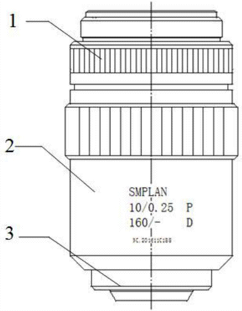
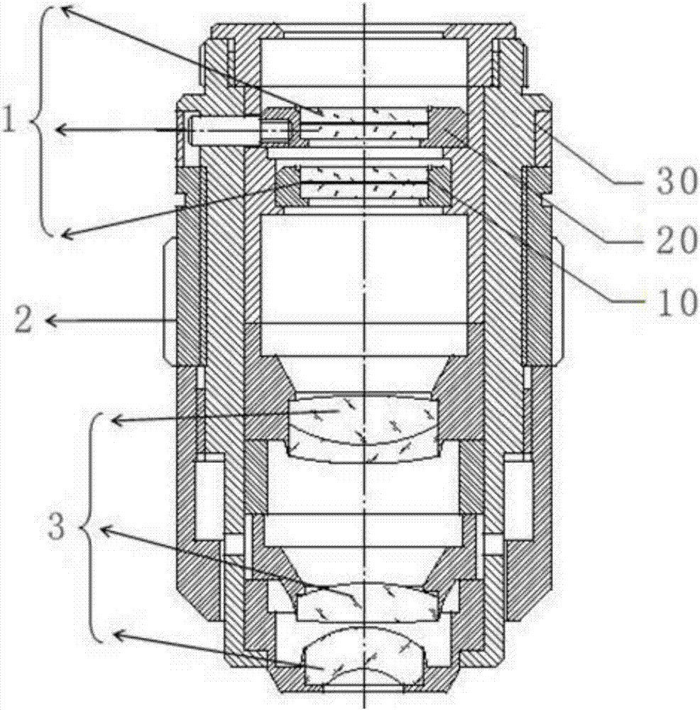
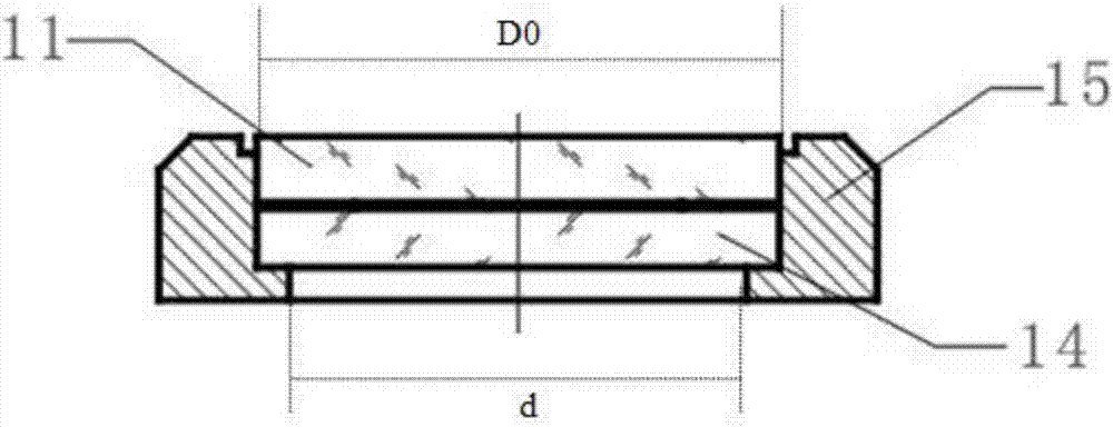
[0031] refer to figure 1 and figure 2 As shown, a kind of adjustable dispersion dyeing microscopic objective lens, metal mirror housing 2, the dispersion dyeing modulator group 1 installed on the inner top of the mirror housing 2, the optical lens group 3 installed on the inner bottom of the mirror housing 2, the dispersion dyeing The modulator group 1 includes a dispersion dyeing polarizer 10, a dispersion dyeing analyzer 20 and an adjuster 30, and the dispersion dyeing analyzer 20 and the dispersion dyeing polarizer 10 are installed side by side in the adjuster 30 up and down, and the dispersion The dyed polarizer 20 is installed directly above the dispersion dyed polarizer 10 . The adjustable dispersion dyeing microscopic objective adopts a 10X microscopic objective lens, and its main technical parameters are: numerical aperture 0.25, and the distance between the rear focal plane of th...


PUM

PropertyMeasurementUnit
wavelengthaaaaaaaaaa
reflectanceaaaaaaaaaa

Abstract

The invention provides a modulated dispersion dyeing microscopic object lens. The object lens comprises a lens housing, a dispersion dyeing modulator group installed on the top end in the lens housing and an optical lens group installed on the bottom end in the lens housing. The dispersion dyeing modulator group comprises a dispersion dyeing polarizer, a dispersion dyeing polarization analyzer and an adjustor. The dispersion dyeing polarizer and the dispersion dyeing polarization analyzer are up-down parallelly installed in the adjustor. The dispersion dyeing polarization analyzer is installed right above the dispersion dyeing polarizer. According to the invention, by introducing the polarized light modulation technology, through light intensity change of linear polarized light under different polarization states, the transmissivity of central light beams is modulated, thus, change of the dispersion dyeing intensity is achieved and qualitative micro-examination of micro feature difference characteristics of an object is achieved.

Description

technical field [0001] The present invention relates to a microscopic objective lens, in particular to a method that uses linearly polarized light to show light intensity changes under different polarization states, thereby modulating the change of the central beam transmittance of the microscopic objective lens, so as to form a modulable optical fiber with different dispersion dyeing effects. Dispersion dyed microscope objectives. Background technique [0002] The traditional dispersion dyeing objective lens is loaded with a ring or circular opaque baffle on the rear focal plane of the microscope objective lens. If it is ring-shaped, the central beam will be transmitted; if it is a central circular baffle, the beam can only be transmitted by Permeate around, when the refractive index of the particle and the immersion liquid are different, dispersion occurs, so that the sample image shows different colors, that is, the dispersion dyeing microscopic observation method. The l...

Claims


Application Information

Patent Timeline
Patent Type & Authority Applications(China)
IPC IPC(8): G02B21/02G02B7/02G02B7/00G01B11/24G01N21/95
CPCG02B7/00G02B7/02G02B21/02G01B11/24G01N21/95
Inventor 李弥高刘文新黄敏健李天明易智敏
Owner GUANGZHOU LISS OPTICAL INSTR
Why Eureka
Try Eureka