
Display device with pressure sensing function

A display device and pressure technology, applied in the input/output process of data processing, instruments, electrical digital data processing, etc., can solve the problem of pressure sensing sensitivity reduction and achieve the effect of improving sensitivity

Inactive Publication Date: 2017-06-20
INTERFACE TECH CHENGDU CO LTD +1
View PDF6 Cites 0 Cited by
  • Summary
  • Abstract
  • Description
  • Claims
  • Application Information

AI Technical Summary

Problems solved by technology

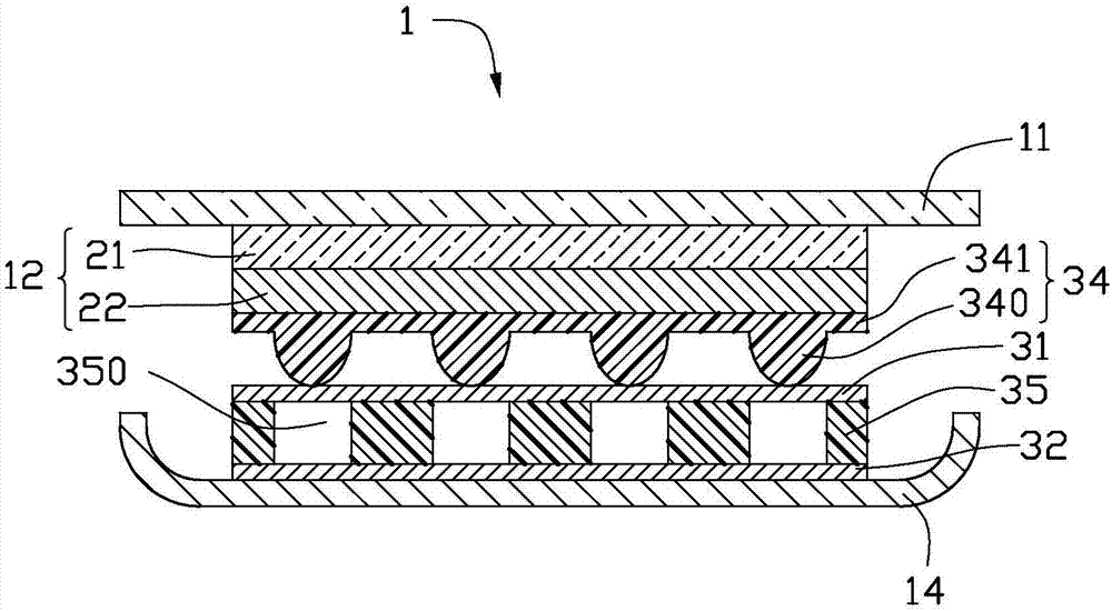
[0005] The display device of the present invention uses an elastic insulating layer as the dielectric layer of the capacitor to ensure the size of the distance between the sensing electrode and the reference electrode, and effectively solve the pressure sensing caused by the small distance between the sensing electrode and the reference electrode due to assembly tolerances. The problem of reduced sensitivity; at the same time, a dual-capacitor series sensing structure is adopted, and the first insulating layer with bumps and the second insulating layer with gaps cooperate with each other to further improve the sensitivity of pressure sensing

Method used


Image

  • Display device with pressure sensing function
  • Display device with pressure sensing function
  • Display device with pressure sensing function

Examples


Embodiment Construction

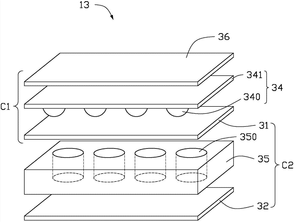
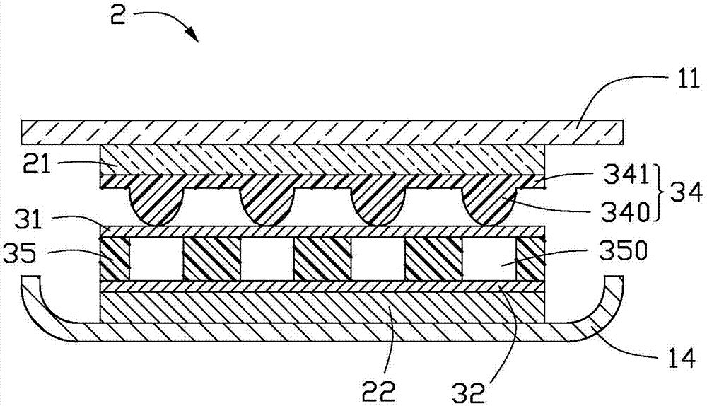
[0013] see figure 1 , figure 1 is a schematic cross-sectional view of the display device 1 according to the first embodiment of the present invention. The display device 1 includes a cover plate 11 , a display module 12 , a first insulating layer 34 , a first sensing electrode 31 , a second insulating layer 35 , a second sensing electrode 32 and a middle frame 14 stacked in sequence. The first insulating layer 34 includes a body 341 and bumps 340 disposed on the surface of the body 341 close to the first sensing electrodes 31 . The second insulating layer 35 has a gap 350 corresponding to each of the bumps 340 . That is, the projection of the bump 340 on the second insulating layer 35 is located in the gap 35 . In this embodiment, the bump 340 is hemispherical. The protrusions 340 can also be in other shapes, such as columns. Preferably, both the first insulating layer 34 and the second insulating layer 35 are elastomers, which may be elastic insulating resin or foam. Wh...


PUM


Abstract

The invention discloses a display device, which comprises a display module and a pressure sensing module, wherein the pressure sensing module comprises a reference electrode, a first insulating layer, a first sensing electrode, a second insulating layer and a second sensing electrode which are sequentially stacked; the display module comprises an electric conductor; the reference electrode is any electric conductor in the display module; the first insulating layer and the second insulating layer both have elasticity; the first insulating layer comprises a plurality of bumps which are arranged at intervals; a gap is formed in the position, corresponding to each bump, of the second insulating layer; the reference electrode, the first insulating layer and the first sensing electrode are matched to form a first capacitor; the first sensing electrode, the second insulating layer and the second sensing electrode are matched to form a second capacitor; and the display device carries out pressure sensing according to changes of capacitance values of the first capacitor and the second capacitor.

Description

technical field [0001] The present invention relates to a display device, in particular to a display device with a pressure sensing function. Background technique [0002] In recent years, the pressure sensing function has been widely used in the display field. The display device will integrate the pressure sensing function to sense the pressure of human touch to realize a specific function (such as the Home button of a mobile phone). The pressure sensing function is usually realized by integrating a capacitive structure in the display device. When a human finger presses, the distance between the sensing electrodes of the capacitive structure changes, resulting in a change in capacitance to generate a corresponding electrical signal. In the prior art, air is usually used as the medium between the sensing electrodes. However, in the actual manufacturing process, the existence of assembly tolerances will cause the actual distance between the capacitive sensing electrodes to be...

Claims


Application Information

Patent Timeline
IPC IPC(8): G06F3/041G06F3/044
CPCG06F3/0414G06F3/044
Inventor 郑小兵
Owner INTERFACE TECH CHENGDU CO LTD
Learn More