Narrow bezel mobile terminal
A mobile terminal, narrow frame technology, applied in the field of communication, can solve the problem of wasting space, and achieve the effect of improving performance, saving space, and high screen ratio
- Summary
- Abstract
- Description
- Claims
- Application Information
AI Technical Summary
Problems solved by technology
Method used
Image

Examples
Embodiment 1
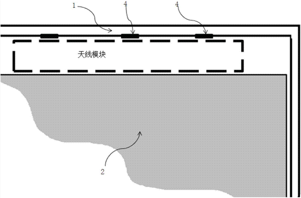
[0027] In view of the large size of the existing antenna module, it is difficult to realize the high screen and narrow frame of the mobile terminal. This example provides a mobile terminal with a narrow frame. Its structure diagram is as follows figure 2 As shown, it includes a non-metal frame 1, a display panel 2, and an extension bar 3. The extension bar 3 is embedded in the non-metal frame 1, and a part or the whole of the extension bar 3 is expanded into a first antenna module. The inner surface of the non-metal frame 1 There is a buckle 4, and there is a clearance area between the non-metal frame 1 and the display panel 2. In this example, the antenna function is realized through the extension bar 3, and the extension bar 3 is embedded in the non-metal frame 1, thereby saving the headroom The space in the area is also conducive to the realization of the performance of the antenna, which can further extend the top of the display panel 2 to the clear area, so as to achieve ...
Embodiment 2
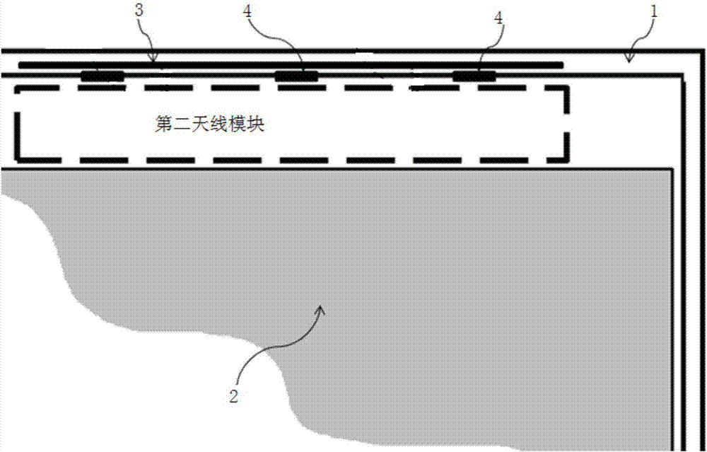
[0032] Based on Embodiment 1, the antenna structure diagram of the mobile terminal in this example is as follows image 3 As shown, in this example, a second antenna module is added in the clearance area. Preferably, the size of the second antenna module is 80mm*7mm*2mm, while the size of the existing antenna module is 80mm*9.5mm*2mm, which is different from the current Compared with some antenna modules, the Y-direction size of the second antenna module in this example is reduced from 9.5mm to 7mm, thereby achieving the purpose of saving the space in the headroom area. By expanding a part of the extension strip 3 into the first antenna module, And by coupling the first antenna module to the second antenna module to achieve the performance of the existing antenna module, and then extending the top of the display panel 2 to the saved headroom area, a high screen-to-body ratio and narrow frame of the mobile terminal can be realized Purpose.
[0033] The return loss diagram of t...
Embodiment 3
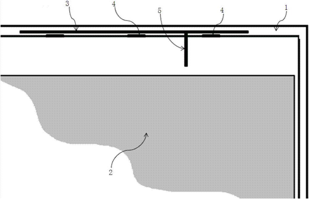
[0036] Based on the second embodiment, the mobile terminal of this example also includes a connection branch 6, the first antenna module is connected to the second antenna module through the connection branch 6, and the number of the connection branch 6 is at least one. The second antenna of this example The module has the same structure and size as the second antenna module in the second embodiment.
[0037] The structural diagram of the extension bar 3 embedded in the non-metallic frame 1 is as follows Figure 6 As shown, the structural diagram of the extension bar 3 pasted on the outer surface of the non-metallic frame 1 is as follows Figure 7 shown.
[0038] This application embeds the extension bar 3 in the non-metal frame 1, or sticks the extension bar 3 on the surface of the non-metal frame 1, and expands the antenna module through the extension bar 3, so as to reduce the Y-direction dimension of the antenna module accordingly, thereby The space occupied by the anten...
PUM
 Abstract
Description
Claims
Application Information
 - R&D
- Intellectual Property
- Life Sciences
- Materials
- Tech Scout
- Unparalleled Data Quality
- Higher Quality Content
- 60% Fewer Hallucinations
Browse by: Latest US Patents, China's latest patents, Technical Efficacy Thesaurus, Application Domain, Technology Topic, Popular Technical Reports.
© 2025 PatSnap. All rights reserved.Legal|Privacy policy|Modern Slavery Act Transparency Statement|Sitemap|About US| Contact US: help@patsnap.com