Combined simple computer circuit board clamping device

A combined and simple technology, applied in the direction of circuits, computer peripheral equipment connectors, connections, etc., can solve the problems that the movable device cannot be replaced independently, the circuit board on the card is unstable, and cannot be stabilized.

Inactive Publication Date: 2017-06-27
广州市新钜电子有限公司
View PDF0 Cites 0 Cited by
  • Summary
  • Abstract
  • Description
  • Claims
  • Application Information

AI Technical Summary

Problems solved by technology

[0003] Although the traditional computer circuit board clamping device can easily eject the card-carrying circuit board, and can effectively protect the electronic components around the combined simple computer circuit board clamping device, yet this traditional computer circuit board clamping device has some shortcoming
First of all, because the fixed end face actually mainly limits the ejection part, but cannot limit the insertion part, and the distance between the rotation center axis and the ejection part is much smaller than the distance between the rotation center axis and the insertion part , in fact, a longer moment arm is formed between the insertion part and the rotation center axis. When the insertion part is rotated, the applied external force acts together with the longer moment arm to generate a larger rotational moment. The force is too strong and the movable device is broken, so that the card-carried circuit board cannot be taken out; secondly, because the installation structure of the rotating central axis of the computer circuit board clamping equipment is a closed structure, and the movable device is generally made of hard materials, so When installing the movable device to the combined simple computer circuit board clamping device, the movable device must be forcibly squeezed with the help of a tool. Once installed, the movable device is difficult to detach from the combined simple computer circuit board clamping device again. And then when the movable device is damaged, the movable device cannot be replaced separately, but the integrated simple computer circuit board clamping device must be replaced, so it is inconvenient to use; in addition, the rear ends of the two side walls of this traditional computer circuit board clamping device There is a gap between them, which reduces the strength of this part, so that the movable device cannot be stably installed in this position, and it will also cause the card-on-board circuit board to be installed unstable, which will affect the reliability of its connection with other circuits

Method used


Image

  • Combined simple computer circuit board clamping device
  • Combined simple computer circuit board clamping device
  • Combined simple computer circuit board clamping device

Examples


Embodiment Construction

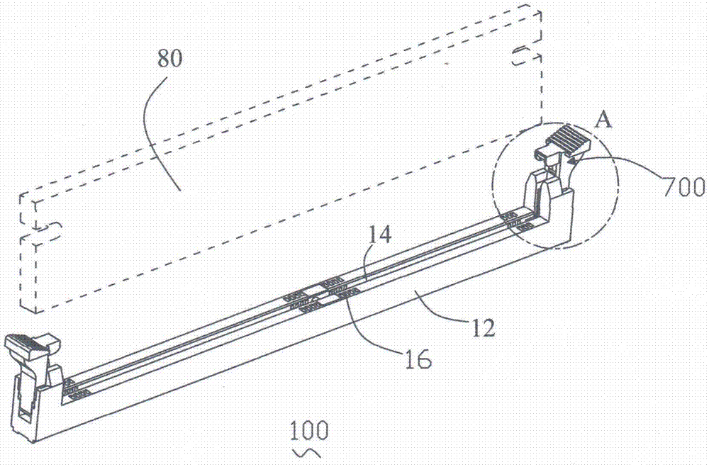
[0018] refer to Figure 1-6 , the combined simple computer circuit board clamping device 100 of the present invention includes a main body 12 for docking the plug-in card 80 and movable devices 700 fixed at both ends of the main body 12 .

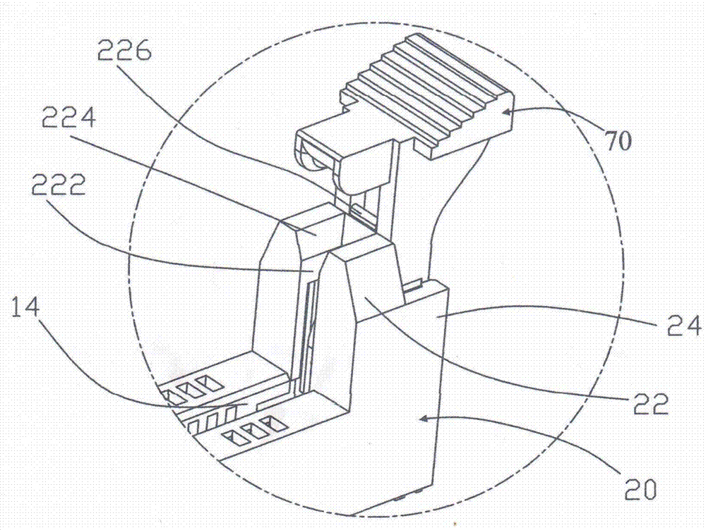
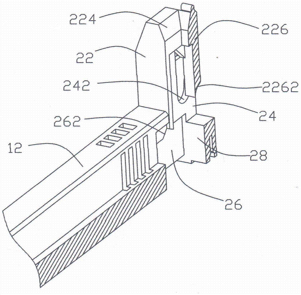
[0019] The center of the main body 12 is provided with a central slot 14 along its length direction, and the two sides of the central slot 14 are provided with contact terminals 16. The two ends of the main body 12 each have a tower-shaped portion 20, and the tower-shaped portion 20 includes a pair of upper parts. 22 and a pair of lower portions 24 adjacent to the pair of upper portions 22 . A clamping groove 222 communicating with the central slot 14 is formed between the two upper parts 22 , and the top opening of the clamping groove 222 forms a slope-shaped guide portion 224 for guiding the plug-in card 80 to be smoothly inserted into the central slot of the main body 12 within 14. A reinforcing horizontal bar 226 is connected between ...


PUM


Abstract

The present invention is a combined simple computer circuit board clamping device, which includes a main body and movable devices fixed at both ends of the main body. The two ends of the main body have tower-shaped parts formed by a pair of upper parts and a pair of lower parts adjacent to the pair of upper parts. , the present invention is a combined simple computer circuit board clamping device with stable and reliable structure and replaceable movable device.

Description

technical field [0001] The invention relates to a circuit connection device, in particular to a combined simple computer circuit board clamping device. Background technique [0002] The computer circuit board clamping device is a connection device widely used in computers or other circuit devices to connect the card-mounted circuit board and the main board circuit to each other, and to facilitate the computer circuit board clamping device and its movable connection. [0003] Although the traditional computer circuit board clamping device can easily eject the card-carrying circuit board, and can effectively protect the electronic components around the combined simple computer circuit board clamping device, yet this traditional computer circuit board clamping device has some shortcoming. First of all, because the fixed end face actually mainly limits the ejection part, but cannot limit the insertion part, and the distance between the rotation center axis and the ejection part...

Claims


Application Information

Patent Timeline
Patent Type & Authority Applications(China)
IPC IPC(8): H01R12/73H01R13/46H01R13/631H01R13/627
CPCH01R12/7023H01R12/721H01R12/737H01R13/46H01R13/631H01R2201/06
Inventor 赵仲普
Owner 广州市新钜电子有限公司
Why Eureka
Try Eureka