Proportioning device for manufacturing brake pad

A brake pad and mounting plate technology, which is applied in the field of batching devices for brake pad manufacturing, can solve the problems of time-consuming, labor-intensive batching, low batching efficiency, and inconvenient batching, etc.

Inactive Publication Date: 2017-07-07
刘世荣
View PDF4 Cites 12 Cited by
  • Summary
  • Abstract
  • Description
  • Claims
  • Application Information

AI Technical Summary

Problems solved by technology

[0005] In order to overcome the disadvantages of inconvenient batching in the current batching device for brake pads, manual stirring is required during batching, time-consuming and labor-intensive addition of different raw materials during the stirring process, and low batching efficiency, the technical problem to be solved by the present invention is to provide a Automatic mixing, segmented batching, time-saving and labor-saving, batching device for brake pad manufacturing with high batching efficiency

Method used


Image

  • Proportioning device for manufacturing brake pad
  • Proportioning device for manufacturing brake pad
  • Proportioning device for manufacturing brake pad

Examples


Embodiment 1

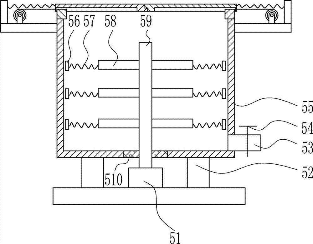
[0041] A batching device for brake pad manufacturing, such as Figure 1-8 As shown, it includes a bottom plate 1, a collection frame 2, a left and right moving mechanism 3, a swing mechanism 4, a stirring mechanism 5, a feeding mechanism 6, a left frame 7, a top plate 8 and a feeding mechanism 9. Frame 2, a left and right moving mechanism 3 is installed in the middle of the top of the bottom plate 1, a stirring mechanism 5 is connected to the top of the left and right moving mechanism 3, a feeding mechanism 6 is connected to the top of the stirring mechanism 5, a left frame 7 and a left frame 7 are installed on the left side of the top of the bottom plate 1 The top is connected with a top plate 8, on which a blanking mechanism 9 is arranged.

Embodiment 2

[0043] A batching device for brake pad manufacturing, such as Figure 1-8 As shown, it includes a bottom plate 1, a collection frame 2, a left and right moving mechanism 3, a swing mechanism 4, a stirring mechanism 5, a feeding mechanism 6, a left frame 7, a top plate 8 and a feeding mechanism 9. Frame 2, a left and right moving mechanism 3 is installed in the middle of the top of the bottom plate 1, a stirring mechanism 5 is connected to the top of the left and right moving mechanism 3, a feeding mechanism 6 is connected to the top of the stirring mechanism 5, a left frame 7 and a left frame 7 are installed on the left side of the top of the bottom plate 1 The top is connected with a top plate 8, on which a blanking mechanism 9 is arranged.

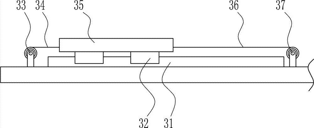
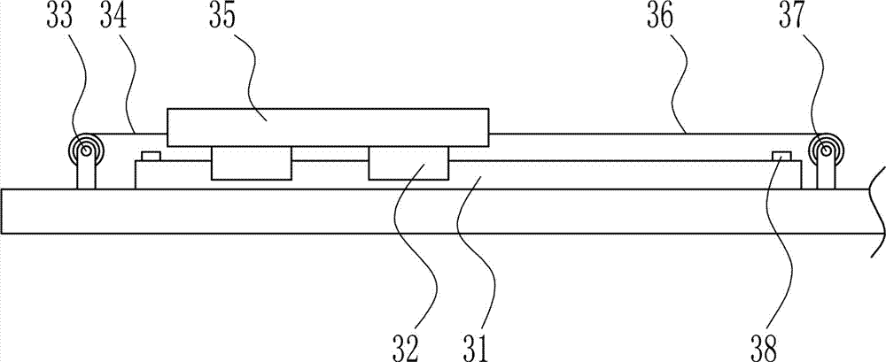
[0044] The left and right moving mechanism 3 includes a first slide rail 31, a first slide block 32, a first electric reel 33, a first backguy 34, a first mounting plate 35, a second backguy 36 and a second electric reel 37 bottom plate ...

Embodiment 3

[0046] A batching device for brake pad manufacturing, such as Figure 1-8 As shown, it includes a bottom plate 1, a collection frame 2, a left and right moving mechanism 3, a swing mechanism 4, a stirring mechanism 5, a feeding mechanism 6, a left frame 7, a top plate 8 and a feeding mechanism 9. Frame 2, a left and right moving mechanism 3 is installed in the middle of the top of the bottom plate 1, a stirring mechanism 5 is connected to the top of the left and right moving mechanism 3, a feeding mechanism 6 is connected to the top of the stirring mechanism 5, a left frame 7 and a left frame 7 are installed on the left side of the top of the bottom plate 1 The top is connected with a top plate 8, on which a blanking mechanism 9 is arranged.

[0047] The left and right moving mechanism 3 includes a first slide rail 31, a first slide block 32, a first electric reel 33, a first backguy 34, a first mounting plate 35, a second backguy 36 and a second electric reel 37 bottom plate ...


PUM


Abstract

The invention relates to a proportioning device and in particular relates to a proportioning device for manufacturing a brake pad. The invention aims to provide the proportioning device for manufacturing the brake pad. The device can stir automatically, proportions in section, and is time- and labor-saving and high in proportioning efficiency. In order to solve the technical problem, the invention provides the proportioning device for manufacturing the brake pad. The proportioning device for manufacturing the brake pad comprises a bottom plate, a collecting frame, a left and right moving mechanism, a swinging mechanism, a stirring mechanism and a feeding mechanism and the like, wherein the collecting frame is arranged on the left side of the top of the bottom plate, the left and right moving mechanism is mounted in the middle of the top of the bottom plate, the top of the left and right moving mechanism is connected to the stirring mechanism, the top of the stirring mechanism is connected to the feeding mechanism, a left rack is mounted on the top of the bottom plate, the top end of the left rack is connected to the top plate, and a blanking mechanism is arranged on the top plate. The device performs blanking in sections by matching the blanking mechanism with the left and right moving mechanism, and the proportioning efficiency of a brake pad raw material is increased by means of the stirring mechanism.

Description

technical field [0001] The invention relates to a batching device, in particular to a batching device for brake pad manufacture. Background technique [0002] Brake pads are also called brake pads. In the braking system of a car, the brake pads are the most critical safety parts. The brake pads play a decisive role in the quality of all braking effects, so good brake pads are the protectors of people and cars. [0003] Due to the different uses of brake pads, the ingredients of brake pads are divided into many types. At present, the batching device of brake pads is inconvenient for batching. Manual mixing is required when batching. Adding different raw materials during the mixing process is time-consuming and laborious, and the batching efficiency is low. Therefore, there is an urgent need to develop a batching device for brake pad manufacturing that can automatically stir, segmented batching, save time and effort, and have high batching efficiency. Contents of the invent...

Claims


Application Information

Patent Timeline
Patent Type & Authority Applications(China)
IPC IPC(8): B01F7/18B01F15/02
CPCB01F27/054B01F27/092B01F27/074B01F27/112B01F27/191B01F27/90B01F35/42B01F35/71731
Inventor 不公告发明人
Owner 刘世荣
Why Eureka
Try Eureka