
Timing method, device and electronic equipment

A technology of timing device and timer, which is applied in the computer field, can solve the problems of complicated use of timer updating main thread UI, updating UI cannot be executed in sub-threads, etc., and achieves the effect of high usability

Active Publication Date: 2020-05-12
WUHAN DOUYU NETWORK TECH CO LTD
View PDF5 Cites 0 Cited by
  • Summary
  • Abstract
  • Description
  • Claims
  • Application Information

AI Technical Summary

Problems solved by technology

The scenario we often use is to start the timer and dynamically update the interface elements after the timer expires. Because the TimerTask timer is executed in the sub-thread after the timer expires, but the update UI cannot be executed in the sub-thread, which leads to Android The timer provided by the system is more complicated to use to update the main thread UI

Method used


Image

  • Timing method, device and electronic equipment
  • Timing method, device and electronic equipment
  • Timing method, device and electronic equipment

Examples


no. 1 example

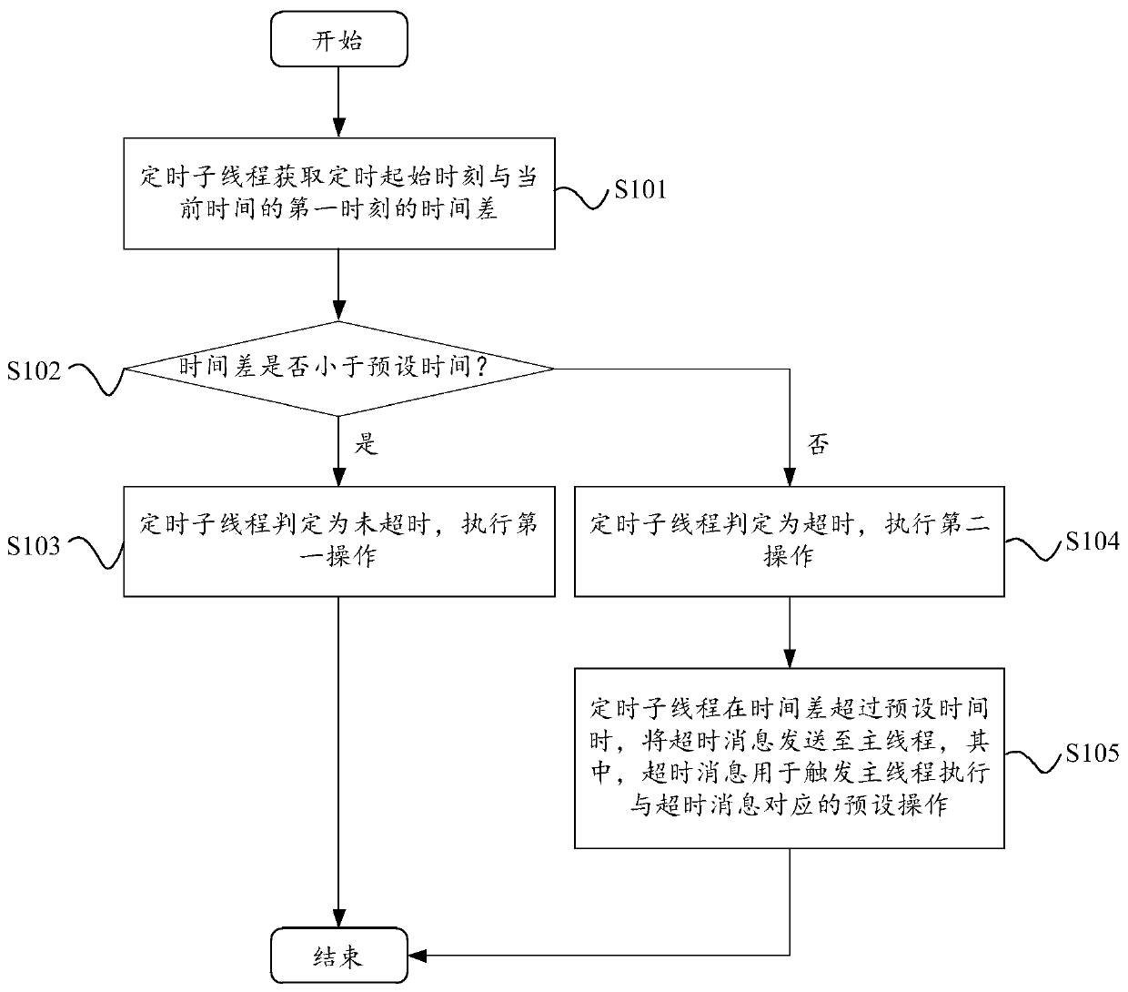
[0027] Please refer to figure 2 , figure 2 The flow chart of the timing method provided by the preferred embodiment of the present invention is shown. The timing method includes the following steps:

[0028] In step S101, the timer sub-thread acquires the time difference between the timing start moment and the first moment of the current time.

[0029] In the embodiment of the present invention, the timing start time may be, but not limited to, the time of the current operating system when the timer is first started, for example, the time of the operating system when the timer is first started is "09:00:00", Then the timing start time is "09:00:00".

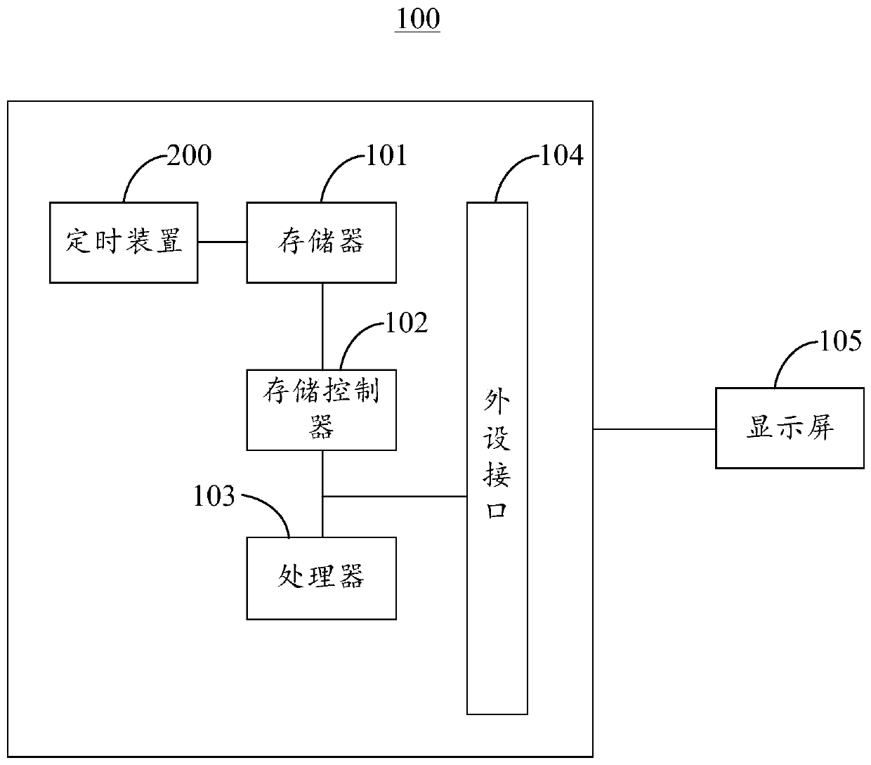
[0030] In the embodiment of the present invention, the first moment of the current time may be, but not limited to, the moment currently displayed on the display screen 105 of the electronic device 100 after the timer is turned on and set for a period of time. This moment may be provided by the operating system Interface ac...

no. 2 example

[0065] Please refer to Figure 4 , Figure 4 A schematic block diagram of a timing device 200 provided by a preferred embodiment of the present invention is shown. The timer device 200 includes a time difference acquisition module 201 , a timing judgment module 202 , a first execution module 203 , a second execution module 204 and a timing trigger module 205 .

[0066] The time difference acquiring module 201 is configured to acquire the time difference between the timing start moment and the first moment of the current time.

[0067] In the embodiment of the present invention, the time difference acquiring module 201 may be used to execute step S101.

[0068] Timing judging module 202, configured to judge whether the time difference is less than a preset time.

[0069] In the embodiment of the present invention, the timing judging module 202 may be used to execute step S102.

[0070] The first execution module 203 is configured to determine that the timing sub-thread has ...


PUM


Abstract

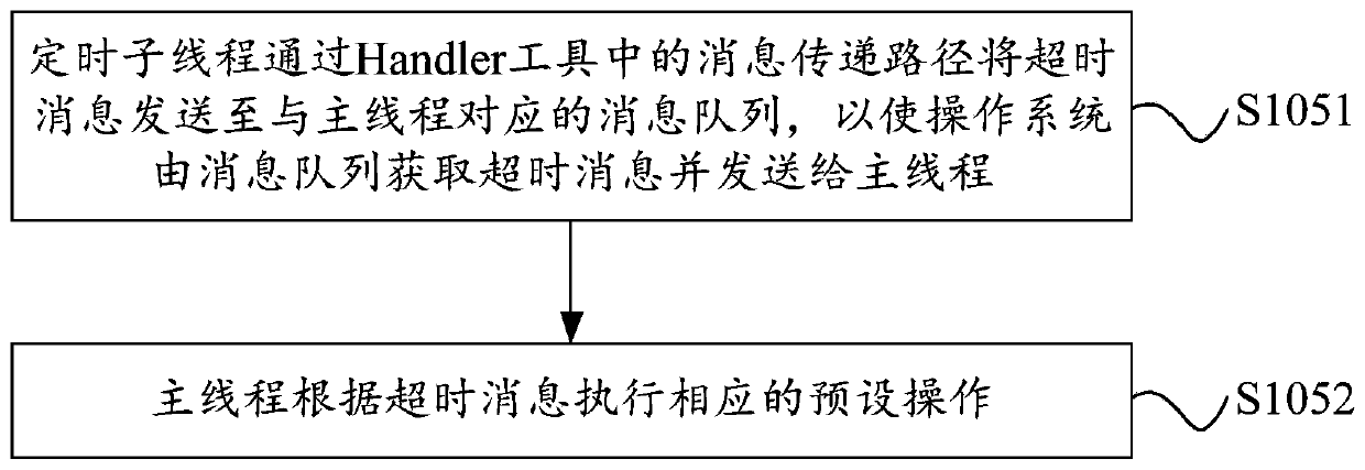
The invention relates to the technical field of computers, and provides a timing method and device and electronic equipment. The method comprises the following steps of: firstly, obtaining a time difference between a timing starting moment and a first moment of the current time by a timing sub-thread; and secondly, sending an overtime message to a main thread by the timing sub-thread when the time difference exceeds a preset time, wherein the overtime message is used for triggering the main thread to execute a preset operation corresponding to the overtime message. According to the method, the overtime message is immediately sent to the main thread after a timer is overtime, and a related operation is executed in the main thread, so that extremely high usability is provided.

Description

technical field [0001] The present invention relates to the technical field of computers, in particular to a timing method, device and electronic equipment. Background technique [0002] A timer is a common tool for implementing timing operations in programs, such as alarm clocks, schedule reminders, and other widely used applications that contain timing trigger logic. The part that implements timing triggering scheduled operations is the timer. [0003] The Android system provides us with a common timer TimerTask. The timer TimerTask provided by the Android system has a feature that the execution process triggered after the timer expires is not executed in the main thread, but in the sub-thread to perform related operations. . The scenario we often use is to start the timer and dynamically update the interface elements after the timer expires. Because the TimerTask timer is executed in the sub-thread after the timer expires, but the update UI cannot be executed in the sub-...

Claims


Application Information

Patent Timeline
Patent Type & Authority Patents(China)
IPC IPC(8): G06F9/54
CPCG06F9/546
Inventor 张磊张文明陈少杰
Owner WUHAN DOUYU NETWORK TECH CO LTD
Learn More