
A detection device for an optical lens

An optical lens and detection device technology, applied in the field of lens detection, can solve the problem that the position of the lens lens cannot be moved, and achieve the effects of facilitating sampling and investigation, improving detection accuracy, and improving efficiency

Active Publication Date: 2021-01-15
新野旭润光电科技有限公司
View PDF18 Cites 0 Cited by
  • Summary
  • Abstract
  • Description
  • Claims
  • Application Information

AI Technical Summary

Problems solved by technology

[0005] The present invention aims at the above-mentioned deficiencies in the prior art, and provides a dismantling and recycling device for power lithium batteries, which solves the problem that the position of the lens inside the lens cannot be moved, so that people can make the sleeve slide in the sliding position by flipping the slip ring. The inner movement of the ring changes the position of the lens inside the sleeve to adjust the focal length of the lens, which is suitable for people to use in different scenes

Method used


Image

  • A detection device for an optical lens
  • A detection device for an optical lens
  • A detection device for an optical lens

Examples


Embodiment 1

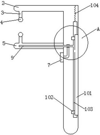
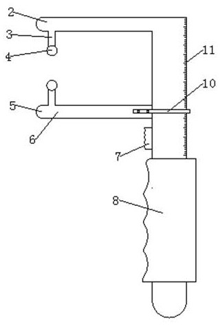
[0025]Such asFigure 1-5As shown, an optical lens detection device for double-concave optical lens detection includes a ruler body 1, a fixed ruler 2 and a movable ruler 5. The top of the ruler body 1 is provided with a fixed ruler 2. The fixed measuring ruler 2 and the ruler body 1 are at right angles, the ruler body 1 is provided with an active measuring ruler 5 under the same side of the fixed measuring ruler 2, the active measuring ruler 5 and the ruler body 1 are at right angles, the active measuring ruler 5 There is an extension rod 9 inside. The ruler body 1 has a slide groove 6 on the same side of the fixed measuring ruler 2, and the extension rod 9 is inserted into the slide groove 6, and the ruler body 1 is below the movable measuring ruler 5 on the same side. A sliding piece 7 is provided, and the sliding piece 7 is fixedly connected to the extension rod 9 through an L-shaped connecting bar 105 arranged inside the ruler body 1, and one end of the L-shaped connecting bar 10...

Embodiment 2

[0027]A detection device for an optical lens, used for the detection of a double-concave optical lens, includes a ruler body 1, a fixed ruler 2 and a movable ruler 5. The top of the ruler body 1 is provided with a fixed ruler 2, and the fixed ruler 2 and the ruler body 1 are at right angles, the ruler body 1 is provided with an active measuring ruler 5 under the same side of the fixed measuring ruler 2, the active measuring ruler 5 is at a right angle to the ruler body 1, and the movable measuring ruler 5 is provided inside An extension rod 9, the ruler body 1 is provided with a slide groove 6 on the same side of the fixed measuring rule 2, the extension rod 9 is inserted into the slide groove 6, and the ruler body 1 is provided with a pusher on the same side of the movable measuring rule 5 The sliding piece 7, the push sliding piece 7 is fixedly connected to the extension rod 9 through an L-shaped connecting bar 105 arranged inside the ruler body 1, and one end of the L-shaped conn...

Embodiment 3

[0030]A detection device for an optical lens, used for the detection of a double-concave optical lens, includes a ruler body 1, a fixed ruler 2 and a movable ruler 5. The top of the ruler body 1 is provided with a fixed ruler 2, and the fixed ruler 2 and the ruler body 1 are at right angles, the ruler body 1 is provided with an active measuring ruler 5 under the same side of the fixed measuring ruler 2, the active measuring ruler 5 is at a right angle to the ruler body 1, and the movable measuring ruler 5 is provided inside An extension rod 9, the ruler body 1 is provided with a slide groove 6 on the same side of the fixed measuring rule 2, the extension rod 9 is inserted into the slide groove 6, and the ruler body 1 is provided with a pusher on the same side of the movable measuring rule 5 The sliding piece 7, the push sliding piece 7 is fixedly connected to the extension rod 9 through an L-shaped connecting bar 105 arranged inside the ruler body 1, and one end of the L-shaped conn...


PUM


Abstract

The invention discloses a detection device of an optical lens. The detection device comprises a ruler body, a fixed measuring ruler and a movable measuring ruler, wherein the fixed measuring ruler isarranged at the top end of the ruler body, the fixed measuring ruler and the ruler body are in a straight angle, the movable measuring ruler is arranged at the bottom, on the same side of the fixed measuring ruler, of the ruler body, an extending rod is arranged inside the movable measuring ruler, a sliding groove is formed at the position, on the same side of the fixed measuring ruler, of the ruler body, the extending rod is inserted into the sliding groove, a push sliding piece is arranged at the position, inside the sliding groove, at the bottom of the movable measuring scale, an L-shaped connecting rod is arranged on one side of the push sliding piece, the end of the L-shaped connecting rod is inserted into the extending rod, a positioning rod is arranged at one end, inside the ruler body, of the extending rod, a positioning groove is formed in the rear side of the positioning rod, the back side of the positioning groove is tightly fixed on the ruler body, ring buckles are arrangedat the two ends of the positioning groove, the ring buckles are arranged outside the positioning rod in a sleeve mode, a ruler is arranged outside the movable measuring ruler in a clamp sleeve mode.According to the detection device, the thickness of different positions of the camera lens can be accurately measured.

Description

Technical field[0001]The invention relates to the field of lens detection, in particular to an optical lens detection device.Background technique[0002]The optical lens is an indispensable part of the machine vision system, which directly affects the quality of imaging and the realization and effect of the algorithm. Optical lenses can be divided into short focal length, medium focal length, and long focal length. From the field of view, there are wide-angle, standard, and telephoto lenses. In terms of structure, there are fixed-aperture fixed-focus lenses and manual-aperture fixed-focus lenses. Automatic iris fixed focus lens, manual zoom lens, automatic zoom lens, automatic iris electric zoom lens, electric three-variable (iris, focal length, focus are variable) lens, etc.[0003]However, the existing optical lens is composed of multiple lenses, and different lenses have different lens effects. In the production process of lens lenses, there are strict requirements on the thickness o...

Claims


Application Information

Patent Timeline
Patent Type & Authority Patents(China)
IPC IPC(8): G01B5/06
CPCG01B5/06
Inventor 刘中勤刘岩勤赵中亮赵海渊刘杰赵迪杨彩珠卢现收沈新国徐威
Owner 新野旭润光电科技有限公司
Learn More