Auxiliary device system applied to swimming

An auxiliary device, a technique for swimmers, applied in the directions of swimming aids, swimming, swimming fins, etc., can solve the problems of uncoordinated leg posture, low forward efficiency, fatigue, etc.

Active Publication Date: 2017-07-14
朱光
View PDF5 Cites 3 Cited by
  • Summary
  • Abstract
  • Description
  • Claims
  • Application Information

AI Technical Summary

Problems solved by technology

[0003] Whether it is a double-footed bifin or a double-footed monofin, it has its most suitable single kicking frequency. Only when the swimmer kicks at this kicking frequency can he obtain the best propulsion; when the swimmer wants to change the swimming speed, For example, when fetching water at a higher frequency for high-speed swimming or swimming at a low speed at a lower frequency, the propulsion efficiency will decrease, especially when the swimmer fetches water at a higher frequency, not only the propulsion efficiency is not high, and get tired very quickly
[0004] Most of the existing swimming equipment and diving equipment are difficult to completely solve the contradiction between the human body's natural structure adapted to walking on land and free swimming in water; since the ancient ancestors of human beings left the ocean and came to live on land, the body structure slowly Slowly changing, the original structure adapted to swimming in the ocean gradually degenerates and disappears, and is replaced by a

Method used


Image

  • Auxiliary device system applied to swimming
  • Auxiliary device system applied to swimming
  • Auxiliary device system applied to swimming

Examples


Embodiment 1

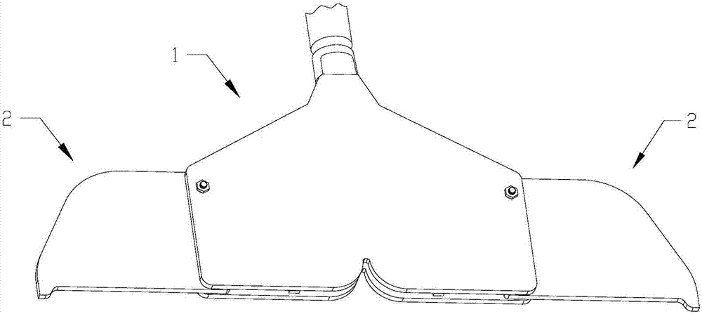
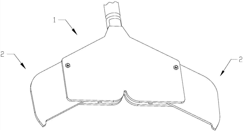
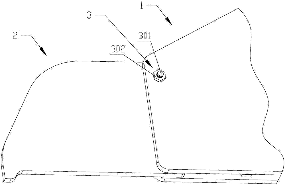
[0189] Embodiment one: if Figure 26 , Figure 28, Figure 31 , Figure 36 As shown, the variable tail fin device part and the balance force applying device part of the present invention can be combined together. The variable tail fin device part mainly includes the main tail fin 1, the auxiliary tail fin 2, the hinge structure 3 of the main and auxiliary fins, and the locking structure of the main and auxiliary fins. Structure 6, the main and auxiliary fin elastic elements 401, the balance force application device part mainly includes the calf rod body 7, the thigh rod body 8, the foot rod body 12, the knee hinge structure 9, the knee elastic energy storage device 10, the ankle hinge structure 13, Ankle elastic energy storage device 14, foot fixing structure 16, pull arm structure 17, calf binding structure 19, thigh binding structure 20, lever arm structure 24; the main and auxiliary fin elastic elements 401 are shrapnel type, and the variable tail fin device part and The p...

Embodiment 2

[0195] Embodiment two: if Figure 27 , Figure 29, Figure 34 , Figure 37As shown, the variable tail fin device part and the balance force applying device part that can be combined together in the present invention, the variable tail fin device part mainly includes the main tail fin 1, the auxiliary tail fin 2, the main and auxiliary fin hinge structure 3, the main and auxiliary fin elastic device 4. Variable caudal fin elastic force adjustment structure 5, main and auxiliary fin locking structure 6, balance force application device mainly includes calf rod body 7, thigh rod body 8, foot rod body 12, knee hinge structure 9, knee elastic energy storage device 10. Ankle hinge structure 13, ankle elastic energy storage device 14, foot fixing structure 16, pull arm structure 17, calf binding structure 19, thigh binding structure 20, lever arm structure 24; different from the structure shown in Embodiment 1 The difference is that the elastic elements 401 of the main and auxiliary...

Embodiment 3

[0202] Embodiment 3: The part of the variable tail fin device and the balanced force applying device of the present invention are realized through a linkage element assembly composed of a mechanical type linkage element and a linkage control module between the auxiliary tail fin 2 and the knee elastic element 1001 mutual linkage, so as to realize the mutual linkage of the variable tail fin device part and the balance force applying device part.

[0203] The linkage control module includes a linkage sensor, a linkage control circuit board, a linkage control power source, and linkage execution components. The linkage sensor includes but is not limited to a displacement sensor that senses a displacement change signal, a stress sensor that senses tensile stress or compressive stress, Linkage control power sources include but not limited to electric motors driven by electric energy. Linkage actuators include but not limited to screw transmission mechanisms that convert the rotationa...


PUM


Abstract

The invention discloses an auxiliary device system applied to swimming. The auxiliary device system comprises a main fail fin, secondary tail fins, a shank rod body and a thigh rod body, wherein at least one secondary tail fin parallel to the main tail fin is arranged on the side of the main tail fin; the secondary tail fins are connected with the main tail fin through a main-secondary fin hinge structure, main-secondary fin elastic components are arranged between the main tail fin and the secondary tail fins; the shank rod body is parallel to the shank of a swimmer and is fixed to at least one shank of the swimmer; the thigh rod body is connected with one end facing to the thigh of the swimmer of the shank rod body; the thigh rod body is parallel to the thigh of the swimmer and is fixed to at least one thigh of the swimmer; a knee hinge structure capable of synchronously bending along with the knee joint of the swimmer is arranged at a junction between the shank rod body and the thigh rod body; at least one knee elastic component for helping the bent knee joint to return is arranged between the shank rod body and the thigh rod body; the secondary tail fins are in mutual linkage with the knee elastic components through at least one linkage component in a mutual relation of actively applying force or passively bearing force.

Description

technical field [0001] The invention relates to swimming equipment and diving equipment industries, in particular to an auxiliary device system for swimming, which is used for swimming and diving sports. It can swim at high speed or roam at low speed, and is especially suitable for long-distance cruise in water. Background technique [0002] In contemporary society, swimming and diving are becoming more and more popular, and various swimming equipment and diving equipment emerge in endlessly. The vast majority of swimming equipment and diving equipment use fins as the main propulsion tool. Double-footed monofins, double-footed double-finned swimmers wear a flipper on each foot, and the swimmer generates forward propulsion by alternately hitting the water with their legs. Double-footed monofins mean that swimmers wear one flipper on both feet , the swimmer generates forward propulsion by kicking the water synchronously with both legs. [0003] Whether it is a double-footed b...

Claims


Application Information

Patent Timeline
IPC IPC(8): A63B31/11A63B31/12A63B31/16
CPCA63B31/11A63B31/12A63B2244/20A63B2225/09
Inventor 朱光
Owner 朱光
Why Eureka
Try Eureka