manual reversing valve

A manual reversing valve and spool technology, applied in fluid pressure actuators, servo motor components, mechanical equipment, etc., can solve the problems of small electromagnet thrust, spool locking, high cost of use, etc., and achieve high stroke control accuracy , reduce wear and simple structure

Active Publication Date: 2019-04-02
ZHUZHOU JIACHENG TECH DEV CO LTD
View PDF7 Cites 0 Cited by
  • Summary
  • Abstract
  • Description
  • Claims
  • Application Information

AI Technical Summary

Problems solved by technology

However, the current control safety system is not high, the thrust of the electromagnet is small, and the valve core is often stuck, causing the electromagnet to push the valve core. In the process, it is often necessary to install a manual reversing device to cooperate with it to realize the function of an emergency switch when the solenoid valve is powered off, and the overall use cost is much higher than that of the manual reversing valve.

Method used


Image

  • manual reversing valve
  • manual reversing valve
  • manual reversing valve

Examples


Embodiment Construction

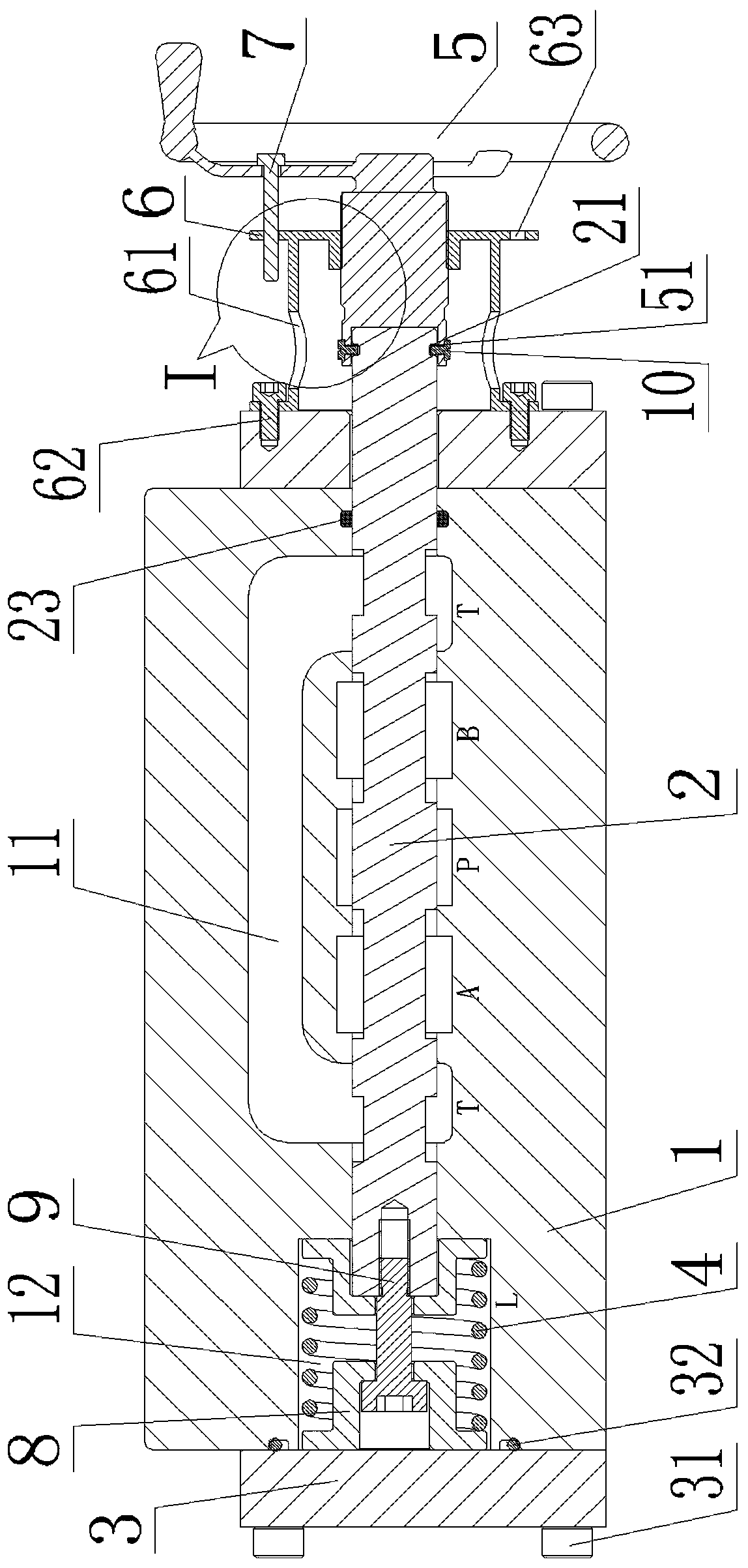
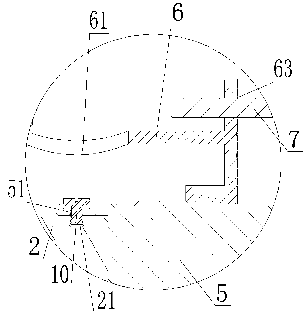
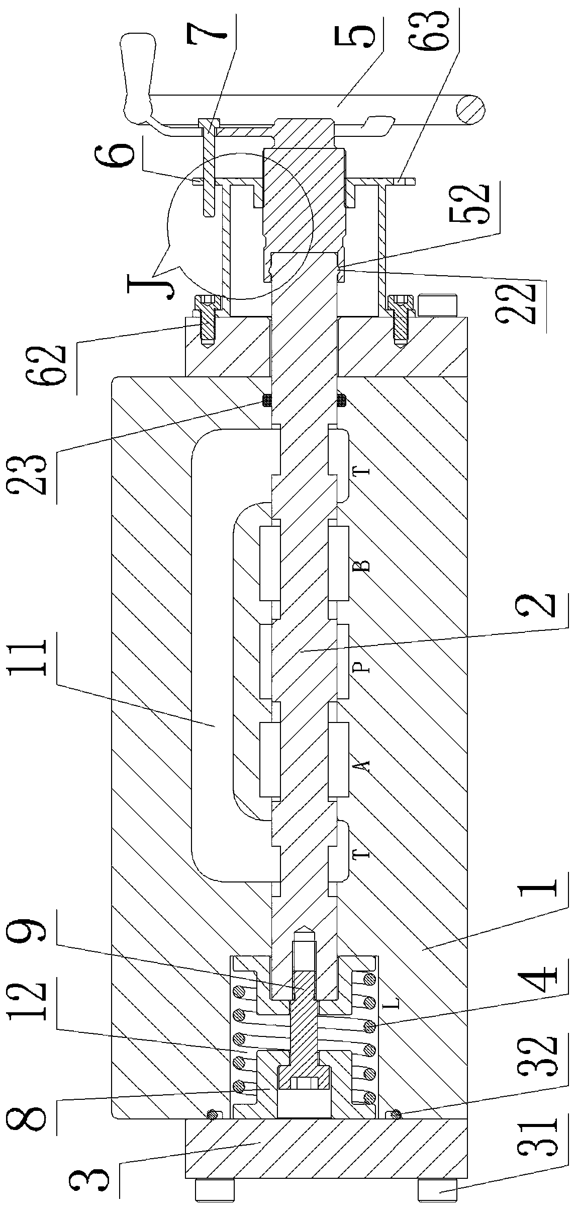
[0023] Taking the three-position four-way hydraulic valve as an example, from figure 1 and image 3 It can be seen that the manual reversing valve of the present invention includes a valve body 1, a valve core 2, an end cover 3, a return spring 4, an adjustment handle 5, a positioning disc 6, a positioning pin 7, a spring seat 8 and a fastening screw 9 , wherein, the end cap 3 includes a left end cap and a right end cap, the left and right end caps are all affixed to both ends of the valve body 1 through a number of end cap bolts 31, and the left end cap is sealed with the valve body 1 through an O-ring 32, in A control chamber 11 and a reset chamber 12 are opened in the valve body 1 along the axial direction from left to right. The valve core 2 is installed in the valve body 1 and runs through the control chamber 11 and the reset chamber 12. There are P port and T port on the top, and A port and B port are provided on the valve core 2 corresponding to P port and T port. The...


PUM


Abstract

The invention discloses a hand-operated reversing valve which comprises a valve body, a valve element, two end covers, a reset spring and an adjustment handle. The adjustment handle is connected to one end of the valve element to drive the valve element to move in the valve body to control communication of an oil way, the reset spring is installed at the other end of the valve element and at the position, between the end covers, in the valve body to drive the valve element to reset, and the end cover located on one side of the adjustment handle is fixedly connected with a positioning disc; the valve element stretches out of the end covers to be in axially-rotary connection with the adjustment handle, and the adjustment handle is connected to the axis of the positioning disc in a threaded manner; a positioning pin is inserted between the adjustment handle and the positioning disc, the adjustment handle is rotated to drive the valve element to axially move in the valve body to achieve oil way communication, the positioning pin is inserted, and positioning of the valve element at different stroke positions is achieved through control over rotation and positioning of the adjustment handle on the positioning disc. The hand-operated reversing valve is simple in structure, low in cost, high in stroke control precision and capable of effectively reducing wear between the valve element and the valve body, stepless speed regulation can be basically achieved, advantages of hand operation and electric operation are combined, and the hand-operated reversing valve is more reasonable and practical.

Description

technical field [0001] The invention relates to a manual reversing valve. Background technique [0002] The reversing valve is a directional control valve with more than two flow forms and more than two oil ports. It is a valve that realizes the communication, cutting and reversing of hydraulic oil flow, as well as pressure unloading and sequential action control. It can be divided into manual reversing Directional valves, electromagnetic directional valves and electro-hydraulic directional valves. [0003] The manual reversing valve is a reversing valve that uses a manual rod to manipulate the valve core to change positions, mainly including spring automatic reset and spring steel ball positioning. The way of spring return, when the outside world cancels the push force on the pull rod, the valve core will automatically reset due to the push force of the spring, and cannot be fixed at a specific stroke position. The method of steel ball positioning can only be positioned a...

Claims


Application Information

Patent Timeline
Patent Type & Authority Patents(China)
IPC IPC(8): F15B13/02
CPCF15B13/02
Inventor 彭彪
Owner ZHUZHOU JIACHENG TECH DEV CO LTD
Why Eureka
Try Eureka