Electronic expansion valve and its refrigeration system

A technology for electronic expansion valves and valve ports, which is applied to components with teeth, valve operating/release devices, valve lifts, etc., which can solve the problem of increasing the volume of gear reducers, increasing the outer diameter of large gears, and failing to achieve high Accuracy, miniaturization and other issues to achieve the effect of improving stroke control accuracy and increasing the flow adjustment range

Active Publication Date: 2021-10-01
ZHEJIANG SANHUA INTELLIGENT CONTROLS CO LTD
View PDF5 Cites 0 Cited by
  • Summary
  • Abstract
  • Description
  • Claims
  • Application Information

AI Technical Summary

Problems solved by technology

There are two ways to increase the reduction ratio: one is to increase the reduction ratio of the gears at all levels, that is, to increase the number of teeth of the large gear, but the above structure will inevitably lead to an increase in the outer diameter of the large gear, resulting in an increase in the volume of the gear reducer. Big
The other is to increase the number of stages of gear reduction, but the above structure will inevitably lead to an increase in the number of gears, which will also lead to an increase in the volume of the gear reducer
In the end, the requirements of high precision and miniaturization cannot be met
In addition, the increase in the number of stages will also lead to a decrease in the transmission efficiency and stability of the entire system
At the same time, there is room for improvement in the structure of the gearbox

Method used


Image

  • Electronic expansion valve and its refrigeration system
  • Electronic expansion valve and its refrigeration system
  • Electronic expansion valve and its refrigeration system

Examples


Embodiment Construction

[0025] It should be noted that, in the case of no conflict, the embodiments in the present application and the features in the embodiments can be combined with each other. The present invention will be described in detail below with reference to the accompanying drawings and examples.

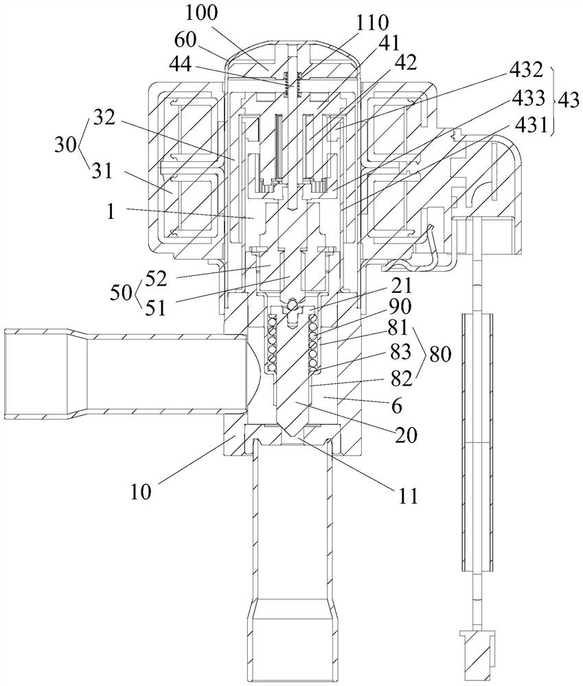
[0026] Such as Figure 3 to Figure 10 As shown, the electronic expansion valve of this embodiment includes: a valve seat 10, a valve needle 20, a drive mechanism 30, a planetary gear reduction mechanism 40, and a transmission mechanism 50, wherein the valve seat 10 has a cavity 6 and a valve communicating with the cavity 6 Valve port 11. The valve needle 20 is movably disposed in the cavity 6 , and the valve needle 20 has an open position for opening the valve port 11 and a closed position for blocking the valve port 11 . The driving mechanism 30 includes a rotor 32 and a coil 31 surrounding the outer side of the rotor 32 . Planetary gear reduction mechanism 40 comprises planet carrier 41, p...


PUM


Abstract

The invention provides an electronic expansion valve and a refrigeration system with the same. Among them, the electronic expansion valve includes: valve seat; valve needle, with open and closed positions; driving mechanism, including rotor and coil; planetary gear reduction mechanism, including planet carrier, planet wheel and gearbox, rotor, planet carrier and gearbox Coaxial setting, the rotor is fixedly connected with the planetary carrier to drive the planetary carrier to rotate along its axis, the planetary gear is sleeved on the first installation shaft, the gearbox includes a box body, a fixed ring gear and an output ring gear, and the planetary gear is simultaneously connected with the The fixed ring gear meshes with the output ring gear; the transmission mechanism includes a nut and a screw rod, the first end of the screw rod is fixedly connected with the output ring gear ring, and the second end of the screw rod abuts against the valve needle so that the valve needle Moves between an open position and a closed position. The application of the technical solution of the present invention can effectively solve the problem that the electronic expansion valve in the prior art cannot meet the requirements of high precision and miniaturization while increasing the flow adjustment range.

Description

technical field [0001] The invention relates to the field of refrigeration, in particular to an electronic expansion valve and a refrigeration system having the same. Background technique [0002] figure 1 A typical deceleration electronic expansion valve structure is shown. The deceleration electronic expansion valve for inverter air conditioner is mainly composed of two parts, one part is the valve body part for flow regulation, and the other part is the coil part for driving. The coil part includes: permanent magnet stepper motor 1', gear reducer 2' with three-stage reduction, threaded secondary structure 5' that converts the motor's rotational motion into the vertical motion of the screw rod 3', and the valve body includes a valve seat 10', and core components such as the spring 7 that controls the lift of the valve needle 8. The working principle of the above-mentioned electronic expansion valve is introduced below: First, the electronic controller of the air conditio...

Claims


Application Information

Patent Timeline
Patent Type & Authority Patents(China)
IPC IPC(8): F16K1/00F16K31/06F16K31/53F16K31/50F16H1/32F25B41/35F25B41/34
CPCF16K31/53F16K31/50F16H1/20F16H2057/02034F16H57/08F16H57/0006F25B41/35Y02B30/70F16K27/048F16H57/02F16K31/502
Inventor 不公告发明人
Owner ZHEJIANG SANHUA INTELLIGENT CONTROLS CO LTD
Why Eureka
Try Eureka