
High-performance magnetic liquid sealing structure

A technology of magnetic liquid and sealing structure, which is applied in the direction of engine sealing, engine components, mechanical equipment, etc. It can solve the problems of increasing flow resistance, poisonous and harmful high-pressure medium gas cannot be used, and the gas medium will not be prevented from escaping.

Active Publication Date: 2016-04-06
ZIGONG ZHAOQIANG ENVIRONMENTAL PROTECTION TECH
View PDF8 Cites 12 Cited by
  • Summary
  • Abstract
  • Description
  • Claims
  • Application Information

AI Technical Summary

Problems solved by technology

[0002] The high-performance magnetic liquid sealing device is suitable for the sealing of conveying medium gas in the fields of petroleum, chemical industry, mining, machinery, metallurgy, aviation, aerospace, military industry, etc. It is widely used because of its small size and good sealing performance. The traditional seal adopts labyrinth seal , suitable for conveying nitrogen, water vapor, air and other low-pressure medium gases that do not pollute the environment. It cannot be used for conveying toxic and harmful high-pressure medium gases, because the non-contact labyrinth seal is formed between the rotating part and the fixed part. The tortuous gap is sealed by the continuous contraction and expansion of the airflow. Although the structure is simple, the tortuous gap only increases the flow resistance and does not prevent the gas medium from escaping fundamentally. Therefore, it is possible to develop a small volume and non-toxic The sealing device that can completely seal the medium gas has very far-reaching significance

Method used


Image

  • High-performance magnetic liquid sealing structure
  • High-performance magnetic liquid sealing structure

Examples


Embodiment Construction

[0017] Below in conjunction with accompanying drawing, the present invention is described in detail.

[0018] In order to make the object, technical solution and advantages of the present invention clearer, the present invention will be further described in detail below in conjunction with the accompanying drawings and embodiments. It should be understood that the specific embodiments described here are only used to explain the present invention, not to limit the present invention.

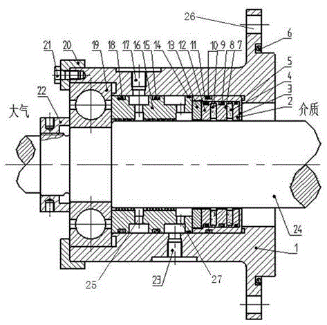
[0019] Such as figure 1 Shown is an embodiment of a high-performance magnetic liquid sealing structure of the present invention. A high-performance magnetic liquid sealing structure includes: a rotating shaft 24, a sealing seat 1 is sleeved on the rotating shaft 24, and one end of the sealing seat 1 There are several connecting holes 26 connected with the cavity to be sealed, the other end of the sealing seat 1 is in contact with the rolling bearing 19, and the rolling bearing 19 is axially limit...


PUM


Abstract

The invention discloses a high-performance magnetic liquid sealing structure, and belongs to magnetic liquid rotary sealing. The high-performance magnetic liquid sealing structure is suitable for conveying high-pressure medium gas at high speed. The sealing structure is composed of a magnetic conductive shaft, a first pole shoe, a second pole shoe, a third pole shoe, a permanent magnet, a sealing seat, an outer hexagonal bolt, a gland, a comb tooth sealing shell, a rolling bearing, a locking thread cover, an inner sleeve shell, an inner gland, a sealing ring and the like. When the pressure of sealed medium gas is high, a magnetic liquid seal needs to be set in multiple stages, thus the space structure is greatly limited, and the defect that the space size of the magnetic liquid seal is limited is overcome. A comb tooth seal is added to the rear end of the magnetic liquid seal, high-pressure air is introduced into a cavity of the comb tooth seal, air pressure balance between the cavity of the comb tooth seal and the interior of a medium end cavity is achieved, the sealing medium is fully sealed, and the sealing space size is saved.

Description

technical field [0001] The invention belongs to the field of construction machinery rotary seals, in particular to a high-performance magnetic liquid seal structure. Background technique [0002] The high-performance magnetic liquid sealing device is suitable for the sealing of conveying medium gas in the fields of petroleum, chemical industry, mining, machinery, metallurgy, aviation, aerospace, military industry, etc. It is widely used because of its small size and good sealing performance. The traditional seal adopts labyrinth seal , suitable for conveying nitrogen, water vapor, air and other low-pressure medium gases that do not pollute the environment. It cannot be used for conveying toxic and harmful high-pressure medium gases, because the non-contact labyrinth seal is formed between the rotating part and the fixed part. The tortuous gap is sealed by the continuous contraction and expansion of the airflow. Although the structure is simple, the tortuous gap only increase...

Claims


Application Information

Patent Timeline
IPC IPC(8): F16J15/43F16J15/16
CPCF16J15/32F16J15/43
Inventor 罗小松颜招强宋敏
Owner ZIGONG ZHAOQIANG ENVIRONMENTAL PROTECTION TECH
Learn More