Novel composite rolling attitude control system and method

A new type of attitude control technology, applied in the field of unmanned aerial vehicles, can solve the problems of inapplicable periodic range change principle, unfavorable control model simplification, and increase the difficulty of problem analysis, so as to reduce the dependence on aerodynamic modeling, improve system availability, The effect of high flight quality and automation

Active Publication Date: 2017-09-29
BEIJING INSTITUTE OF TECHNOLOGYGY
View PDF9 Cites 13 Cited by
  • Summary
  • Abstract
  • Description
  • Claims
  • Application Information

AI Technical Summary

Problems solved by technology

If it is only based on the structure of the rudder surface, for the existing common small and high-speed unmanned aerial vehicles, it is necessary to equip a larger-sized rudder surface with a higher center of gravity to enhance the effect of the rudder surface, which will have a certain impact on the scope of application of the aircraft. restrictions; if it is only based on the swash plate structure, since the present invention is applicable to the tandem double-duct type unmanned aerial vehicle, the rolling force provided by the double-duct type rotor is obviously smaller than that of the open type rotor under the same rotor speed, so the The designed rotor speed exceeds the average speed of the normal open rotor, which is not within the normal range, so the principle of cyclic pitch change alone is not applicable; the swash plate of the existing common aircraft of this type has three degrees of freedom, and the collective pitch and cycle At the same time, it is realized based on the swash plate, which makes different problems coupled together and greatly complicates the analysis of the problem. Therefore, this type of unmanned aerial vehicle is often difficult to design, complicated in mechanism, and difficult for untrained operators to control. When using automatic control technology to develop For such unmanned aerial vehicles, it takes a lot of energy to conduct in-depth analysis of aerodynamic problems in order to obtain sufficient flight quality and ensure its automation level, which is not conducive to the simplification of the control model and also increases the difficulty of problem analysis

Method used


Image

  • Novel composite rolling attitude control system and method
  • Novel composite rolling attitude control system and method
  • Novel composite rolling attitude control system and method

Examples


Embodiment Construction

[0060] In order to make the objectives, technical solutions and advantages of the present invention clearer, the present invention will be further described in detail below in conjunction with embodiments. It should be understood that the specific embodiments described herein are only used to explain the present invention, but not to limit the present invention.

[0061] The application principle of the present invention will be described in detail below with reference to the accompanying drawings.

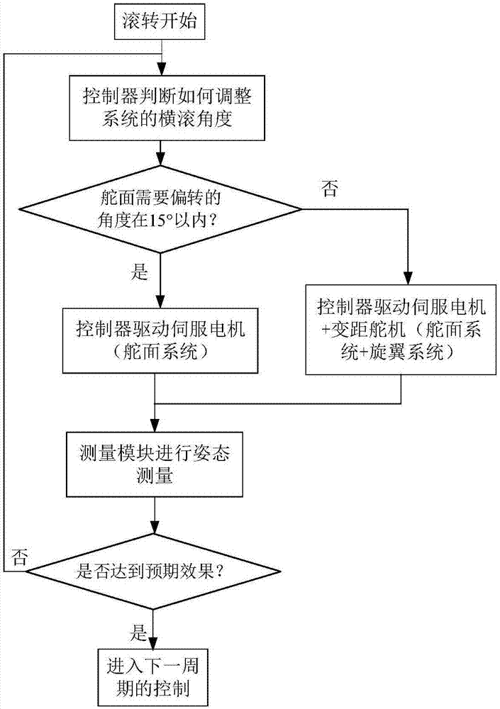
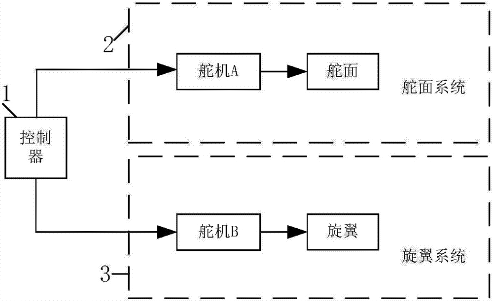
[0062] Such as figure 1 As shown, the new composite roll attitude control method provided by the embodiment of the present invention combines the principle of the rudder surface to adjust the flight attitude and the principle of periodic pitch change of the conventional helicopter swash plate; using redundant control The idea is to control the roll channel of the aircraft through the rudder surface system, perform auxiliary compensation for the roll channel through the rotor system, re...


PUM


Abstract

The invention belongs to the technical field of an unmanned aerial vehicle, and discloses a novel composite rolling attitude control system and method. The control method integrates a principle for adjusting a flight attitude by utilizing a rudder surface and a conventional helicopter tipping tray periodically-pitch-variable principle; by utilizing a redundant control concept, an aerocraft rolling passage is controlled by a rudder system, the auxiliary compensation for the rolling passage is carried out by virtue of a rotary wing system, an airflow direction is limited by virtue of a duct, and the rudder system is controlled; and the control system comprises a controller, a rudder system, a rotary wing system and a duct. The novel composite rolling attitude control system is high in air passing capacity, compact in structure, reasonable in design and capable of realizing automatic hovering and precise attitude control and has advantages of small space size, large effective load, high control response sensitivity, high system stability, high robustness and the like.

Description

Technical field [0001] The invention belongs to the technical field of unmanned aerial vehicles, and in particular relates to a novel composite rolling attitude control system and method. Background technique [0002] The traditional multi-rotor unmanned aerial vehicle changes the attitude of the aircraft by changing the rotation speed of the rotor to realize the control of the roll, pitch and yaw channels. Take a quad-rotor drone as an example. Increasing the lift of one of the rotors on both sides of the forward direction while reducing the lift of the opposite rotor will generate angular acceleration around the x-axis, thereby changing the roll angle of the drone. [0003] With the development of unmanned aerial vehicles, a series of new attitude control structure schemes designed based on the attitude control principles of fixed wings and helicopters have been proposed. The invention patent with the application number 201610359060.1 proposes a mechanism that uses differential ...

Claims


Application Information

Patent Timeline
Patent Type & Authority Applications(China)
IPC IPC(8): B64C13/50B64C19/02
CPCB64C13/50B64C19/02B64U10/10B64U50/14
Inventor 彭怡凡徐彬项昌乐马越张一博樊伟林露
Owner BEIJING INSTITUTE OF TECHNOLOGYGY
Why Eureka
Try Eureka