Optical fiber communication wire connector

A technology of optical fiber communication and connectors, applied in light guides, optics, instruments, etc., can solve the problem of high cost and achieve the effect of low cost and simple structure

Pending Publication Date: 2017-07-14
WEINAN NORMAL UNIV
View PDF14 Cites 2 Cited by
  • Summary
  • Abstract
  • Description
  • Claims
  • Application Information

AI Technical Summary

Problems solved by technology

In the prior art, when the optical fiber is broken, it is necessary to replace the entire line between the two optical fiber devices, which is expensive, so there is room for improvement

Method used


Image

  • Optical fiber communication wire connector

Examples


Embodiment Construction

[0010] The present invention will be further described below in conjunction with accompanying drawing:

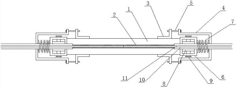
[0011] Such as figure 1 Shown: the present invention includes optical fiber 11, optical fiber outer tube 10, connecting cylinder 1, mirror tube 2, bolt seat 3, compression sleeve 4, tension bolt 5, optical fiber locking seat 6, spring 7, pressure plate 8 and pressure Tighten the bolt 9, the optical fiber outer tube 10 is coated on the optical fiber 11, the mirror tube 2 is located in the connecting cylinder 1, the bolt seat 3 is located outside the connecting cylinder 1, and the optical fiber 11 is located in the In the mirror tube 2, the pressing plate 8 is located in the optical fiber locking seat 6, the pressing bolt 9 is located on the optical fiber locking seat 6, and is in contact with the pressing plate 8, and the optical fiber locking The seat 6 is set on the optical fiber outer tube 10, and fixed by the pressure plate 8 and the compression bolt 9, one side of the ...


PUM


Abstract

The invention discloses an optical fiber communication wire connector, which comprises an optical fiber, an optical fiber outer tube, a connecting cylinder, a mirror tube, a bolt base, a compression sleeve, tightening bolts, an optical fiber locking base, a spring, a pressing plate and a compression bolt, and is characterized in that the optical fiber is externally covered by the optical fiber outer tube, the mirror tube is located in the connecting cylinder, the bolt base is located outside the connecting cylinder, the optical fiber is located in the mirror tube, the optical fiber locking base sleeves the optical fiber outer tube and is fixed through the pressing plate and the compression bolt, one side of the optical fiber locking base is contacted with the connecting cylinder, the other side of the optical fiber locking base is connected with the internal part of the compression sleeve through the spring, and the outer edge of the compression sleeve is connected with the bolt base through the tightening bolts. Compared with the prior art, the optical fiber is connected through the mirror tube, a connection part of the optical fiber is enabled to be perform total-reflection transmission in the mirror tube, the optical fiber is enabled to always keep good butt joint in the mirror tube through the optical fiber locking base, the spring and the compression sleeve, and the optical fiber communication wire connector is simple in structure and low in cost and has popularization and application values.

Description

technical field [0001] The invention relates to an optical fiber communication device, in particular to an optical fiber communication connector. Background technique [0002] Optical fiber, short for optical fiber, is a fiber made of glass or plastic that acts as a means of light transmission. The principle of transmission is 'total reflection of light'. In the prior art, when an optical fiber is broken, the entire line between two optical fiber devices needs to be replaced, which is costly, and therefore there is room for improvement. Contents of the invention [0003] The object of the present invention is to provide an optical fiber communication connector in order to solve the above problems. [0004] The present invention achieves the above object through the following technical solutions: [0005] The invention includes an optical fiber, an optical fiber outer tube, a connecting cylinder, a mirror tube, a bolt seat, a compression sleeve, a tension bolt, an optica...

Claims


Application Information

Patent Timeline
Patent Type & Authority Applications(China)
IPC IPC(8): G02B6/38
CPCG02B6/3801
Inventor 张晓娟
Owner WEINAN NORMAL UNIV
Why Eureka
Try Eureka