
Smoke leakage prevention side suction type range hood convenient to maintain

A side-suction type, range hood technology, applied in the direction of removing soot, heating, household heating, etc., can solve the problems of soot escaping, affecting the fume exhaust effect of the side-suction type range hood, easily blocking soot, etc., to prevent escape. Effect

Pending Publication Date: 2017-07-18
ZHEJIANG PUTIAN ELECTRIC APPLIANCE
View PDF5 Cites 10 Cited by
  • Summary
  • Abstract
  • Description
  • Claims
  • Application Information

AI Technical Summary

Problems solved by technology

[0003] The side-suction range hood is mainly installed against the wall when in use, and there is a large space between the bottom of the front panel of the range hood and the wall. The bottom of the range hood is on the bottom of the range hood, so the wide oil collection cup can easily block the lampblack, and it is easy to cause the lampblack to escape from the oil collection cup to the back of the range hood, which seriously affects the smoke exhaust effect of the side suction range hood
Moreover, the current design structure of the side-suction range hood is not very convenient for maintenance. When the fan fails, the range hood needs to be disassembled completely, and the fan can only be taken out by opening the shell, which is very inconvenient.

Method used


Image

  • Smoke leakage prevention side suction type range hood convenient to maintain
  • Smoke leakage prevention side suction type range hood convenient to maintain
  • Smoke leakage prevention side suction type range hood convenient to maintain

Examples


Embodiment Construction

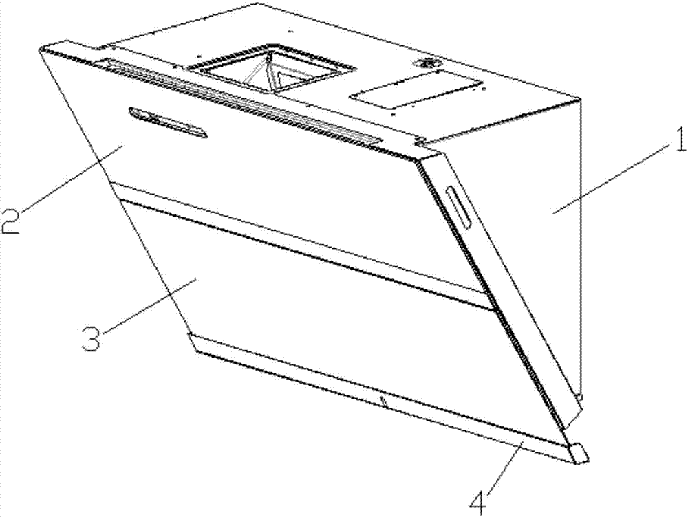
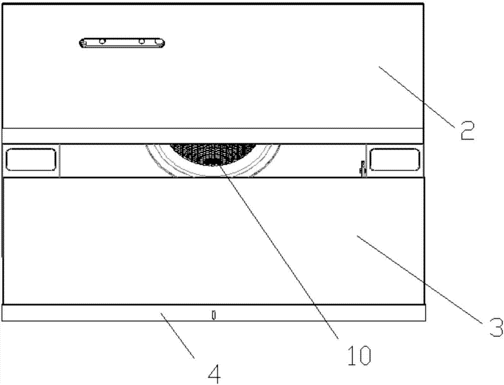
[0019] The present invention provides a side-suction range hood that prevents running smoke and is easy to maintain. The specific structure is as follows: figure 1 with figure 2 As shown, it includes a housing 1 and a front panel, wherein the top surface and the back of the housing 1 adopt a right-angle design structure, which can make the back of the housing 1 tightly contact with the wall when the range hood is installed. At the same time, the front panel is installed inclined downwards to reduce the space between the bottom of the front panel and the wall, further preventing the oil fumes from escaping along the bottom of the front panel to the back of the range hood. The front of the front panel is respectively provided with a main air suction port 10 and an auxiliary air suction port 11 , and the auxiliary air suction port 11 is a mesh structure and is located at the bottom of the main air suction port 10 . In order to prevent the smell of oil fume in the public flue wh...


PUM


Abstract

The invention relates to a smoke leakage prevention side suction type range hood convenient to maintain. The range hood comprises a shell and a front panel. The top face of the shell is perpendicular to the back face of the shell. The front panel is provided with an air suction opening. An upper smoke baffle and a lower smoke baffle which are capable of rising and falling are installed on the front face of the front panel. Two independent drive mechanisms driving the upper smoke baffle and the lower smoke baffle correspondingly are arranged in the shell. An oil collection cup is arranged at the bottom of the lower smoke baffle. After the lower smoke baffle moves downwards, the plane where the lower smoke baffle is located intersects the plane where the back face of the shell is located. The drive mechanisms comprise asynchronous motors installed on the back face of the front panel. Output shafts of the asynchronous motors drive driving gears to rotate. The driving gears mesh with driven gears. The outer diameters of the driving gears and the outer diameters of the driven gears are the same. The back faces of the upper smoke baffle and the lower smoke baffle are each provided with a concave part. The left side walls and the right side walls of the concave parts are each provided with a rack. The driving gears and the driven gears mesh with the racks on the left side walls and the right side walls of the concave parts correspondingly. The side suction type range hood provided by the invention has the characteristics of being convenient to maintain, free of smoke leakage and good in oil smoke suction effect.

Description

technical field [0001] The invention relates to a range hood, in particular to a side-suction type range hood which is smoke-proof and easy to maintain. Background technique [0002] Because the air inlet of the side suction range hood is closer to the source of the oil fume, it can lock the oil fume in the first place, and can effectively shorten the moving distance of the oil fume rising, so the smoke exhaust effect is naturally more ideal. Because it adopts an open design on the appearance of the smoke collection chamber, which increases the range of cooking space, there is no sense of depression when cooking, and it can effectively avoid the occurrence of meeting incidents, so it is more and more favored by consumers. [0003] The side-suction range hood is mainly installed against the wall when in use, and there is a large space between the bottom of the front panel of the range hood and the wall. Therefore, the large oil collecting cup can easily block the oil fume, a...

Claims


Application Information

Patent Timeline
IPC IPC(8): F24C15/20
CPCF24C15/20F24C15/2021F24C15/2085
Inventor 张校豪吴愚
Owner ZHEJIANG PUTIAN ELECTRIC APPLIANCE
Features
  • Generate Ideas
  • Intellectual Property
  • Life Sciences
  • Materials
  • Tech Scout
  • Unparalleled Data Quality
  • Higher Quality Content
  • 60% Fewer Hallucinations
Learn More