
Cable laying equipment

A cable laying and equipment technology, which is applied in the direction of cable laying equipment, transportation and packaging, conveyor objects, etc., can solve the problems of increased manpower consumption, low operating efficiency, and manpower consumption, so as to reduce manpower consumption, improve operating efficiency, reduce The effect of task difficulty

Active Publication Date: 2018-06-08
GUANGZHOU POWER SUPPLY BUREAU GUANGDONG POWER GRID CO LTD
View PDF6 Cites 4 Cited by
  • Summary
  • Abstract
  • Description
  • Claims
  • Application Information

AI Technical Summary

Problems solved by technology

Among them, in the traditional technology, the loading and unloading of the cable coil is carried out manually, which consumes a lot of manpower, which is not conducive to the realization of full automation of cable laying
Moreover, some cable rolls are heavy cables, which are large in size and heavy in weight, which brings a lot of inconvenience to manual operation.
In addition, in the traditional cable retraction work, it is also relying on manpower to pull and rewind the cable.
The cable is dragged on the ground, and the frictional resistance is large, which brings inconvenience to the retracting and unwinding of the cable and increases manpower consumption
Especially in rural and mountainous areas with complex terrain, it also increases the difficulty of manual work, requires a lot of manpower, and the work efficiency is low

Method used


Image

  • Cable laying equipment
  • Cable laying equipment
  • Cable laying equipment

Examples


Embodiment Construction

[0027] In order to make the object, technical solution and advantages of the present invention clearer, the present invention will be further described in detail below in conjunction with the accompanying drawings and specific implementation methods. It should be understood that the specific embodiments described here are only used to explain the present invention, and do not limit the protection scope of the present invention.

[0028] It should be noted that when an element is said to be "fixed" to another element, it may be directly fixed to the other element or may be fixed to the other element through an intermediate element. When an element is referred to as being "connected to" another element, it can be directly connected to the other element or connected to the other element through intervening elements. In addition, unless otherwise specified, the descriptions of the terms "first" and "second" in the specification are only used to distinguish each component, element,...


PUM


Abstract

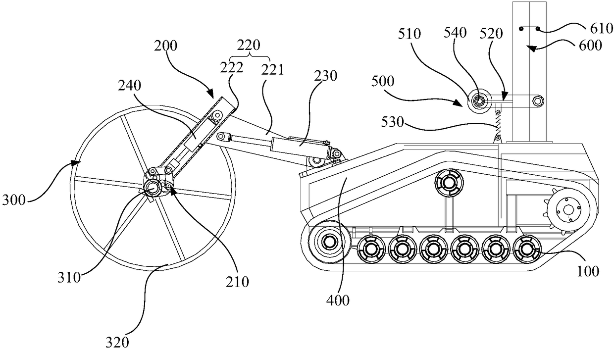
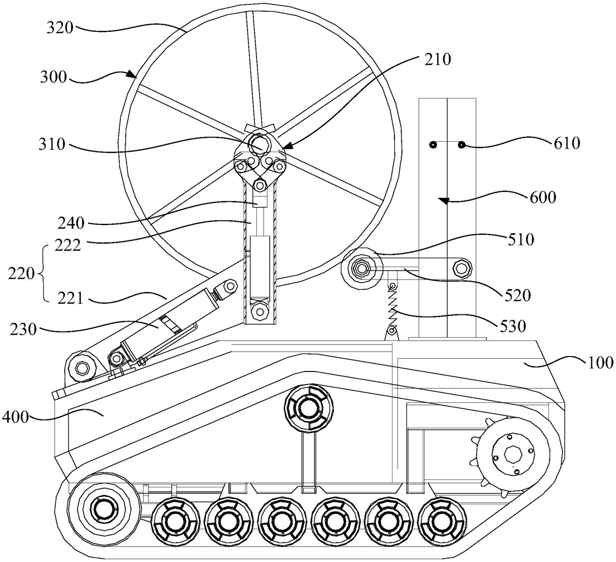
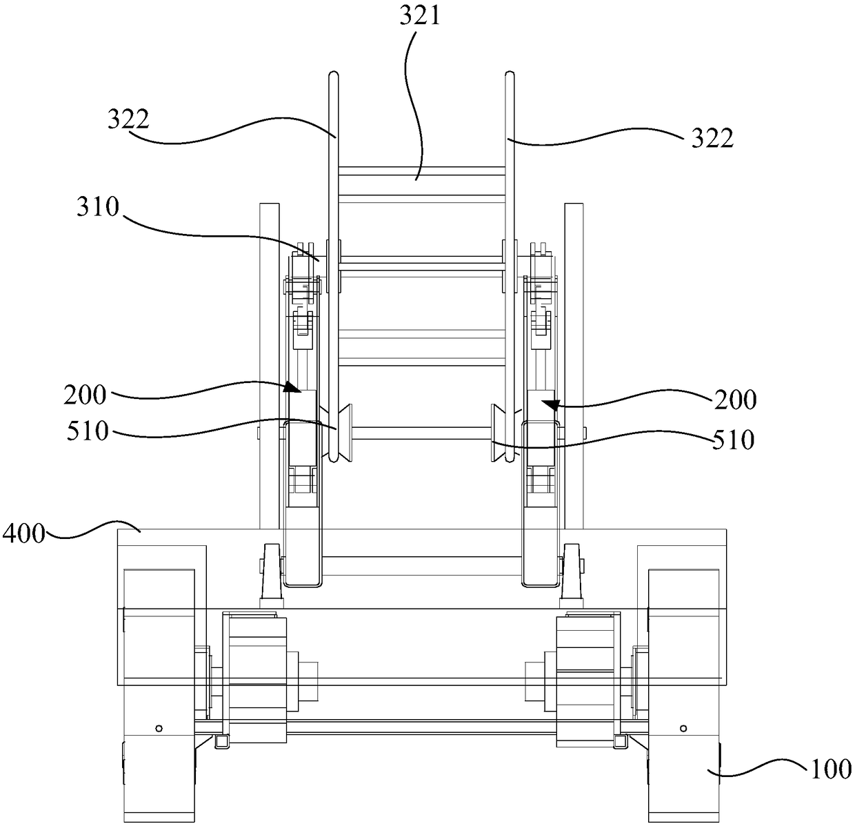
The invention discloses an electric cable laying device comprising a chassis device, a running device arranged on a bottom part of the chassis device, a mechanical arm structure arranged on the chassis device, a first driving device arranged on the chassis device, a control module arranged on the chassis device, wherein the mechanical arm structure is used for grasping or discharging an electric cable roll, and the first driving device is used for driving the grasped electric cable roll to rotate; the running device, the mechanical arm structure and the first driving device are electrically connected with the control module. Via the electric cable laying device, automatically loading, transporting, wind-up operation and pay-off operation of the electric cable roll can be realized; operation efficiency can be improved, and operation difficulty can be lowered.

Description

technical field [0001] The invention relates to the technical field of distribution network cable laying, in particular to a cable laying equipment. Background technique [0002] The current cable construction operation needs to carry out work such as loading, transportation and retracting of cables. Among them, in the traditional technology, the loading and unloading of the cable coil is performed manually, which consumes a lot of manpower and is not conducive to the realization of full automation of cable laying. Moreover, some cable rolls are heavy-duty cables, which are large in size and heavy in weight, which brings a lot of inconvenience to manual operation. In addition, in the traditional cable retraction work, the cable is also pulled and rewound by manpower. The cable is dragged on the ground, and the frictional resistance is large, which brings inconvenience to the retraction and release of the cable and increases manpower consumption. Especially in rural areas,...

Claims


Application Information

Patent Timeline
Patent Type & Authority Patents(China)
IPC IPC(8): H02G1/06B65G47/90
CPCB65G47/904H02G1/06
Inventor 莫文雄王志军罗健斌梁国开
Owner GUANGZHOU POWER SUPPLY BUREAU GUANGDONG POWER GRID CO LTD
Learn More