Filter element and filter system with siphon venting arrangement

A technology of filters and siphons, applied in membrane filters, charging systems, cartridge filters, etc.

Active Publication Date: 2017-07-25
MANN HUMMEL GMBH
View PDF2 Cites 2 Cited by
  • Summary
  • Abstract
  • Description
  • Claims
  • Application Information

AI Technical Summary

Problems solved by technology

This can be disadvantageous, especially in motor vehicles with inter

Method used


Image

  • Filter element and filter system with siphon venting arrangement
  • Filter element and filter system with siphon venting arrangement
  • Filter element and filter system with siphon venting arrangement

Examples


Embodiment Construction

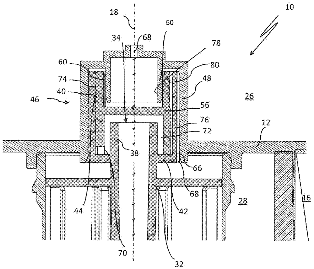
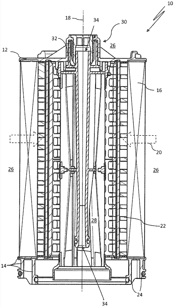
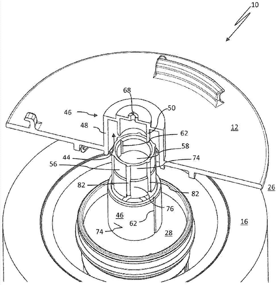
[0029] figure 1A filter element 10 is shown for filtering out contaminants contained in a liquid medium, in this case fuel. The filter element 10 is provided as an exchangeable wear part for a filter housing of a liquid filter not shown in greater detail. In its operative position, the filter element 10 has upper first and lower second end plates 12, 14 between which a filter medium 16 is disposed for filtering out fuel. Contains particulate pollutants. The filter medium 16 is arranged in an annular manner with respect to a central or longitudinal axis 18 of the filter element and can in particular be arranged in the form of a star-shaped corrugated bellows. The filter media 16 is bonded to the end plates 12, 14 at both ends or remains embedded in the material of the end plates 12, 14 in a fluid-tight manner. In operation (ie, filter operation), liquid medium may flow from radially outer to radially inner through the filter media in a main flow direction extending radially ...


PUM


Abstract

The present invention relates to a filter element for a liquid medium having a filter medium disposed in an annular manner with respect to a longitudinal axis of the filter element. The filter element further comprises: an end plate which is an upper end plate when the filter element is operated and a lower end plate. The filter medium is held between the upper end plate and the lower end plate, wherein the filter front side which is arranged at an upstream part of the fluid of the filter medium and a filter rear side of the filter element which is arranged at a downstream part of the fluid of the filter medium are defined via the filter medium. The filter element also has a ventilation device comprising: a first ventilation passage connected to the filter front side of the filter element at the inlet end; a vent pipe or a vent pipe portion. The filter element has a siphon, the first vent channel being fluidly connected to the inlet opening of the vent pipe or vent pipe portion by means of a siphon so as to prevent undesirable reflow of air from the vent tube.

Description

technical field [0001] The invention relates to a filter element for liquid media, especially fuel, having a filter medium arranged in an annular manner with respect to the longitudinal axis of the filter element, and also having an end plate, which when the filter element is in operation is an upper end plate; and a lower end plate between which the filter media is held, wherein the filter front side disposed fluidly upstream of the filter media and the filter media disposed fluidly downstream of the filter media The filter rear sides of the filter elements are delimited from one another by the filter medium. The filter element has a ventilation device comprising a first ventilation channel fluidly connected at the inlet end to the filter front side of the filter element and also comprising a ventilation duct below which The direction of the upper end plate extends axially away from the upper end plate and has an inlet opening at one end and an outlet opening at the other en...

Claims


Application Information

Patent Timeline
IPC IPC(8): B01D35/01B01D35/30B01D27/08F02M37/22
CPCB01D27/08B01D35/005B01D35/30B01D36/001F02M37/22B01D36/003B01D29/21B01D2201/295B01D2201/4046B01D2201/347B01D29/11
Inventor M.魏因多夫I.拉兹加尼P.特劳特曼B.纳格尔丁格
Owner MANN HUMMEL GMBH
Why Eureka
Try Eureka