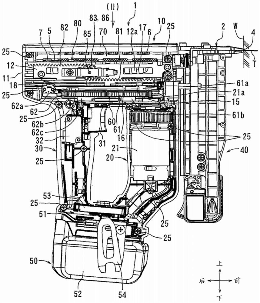
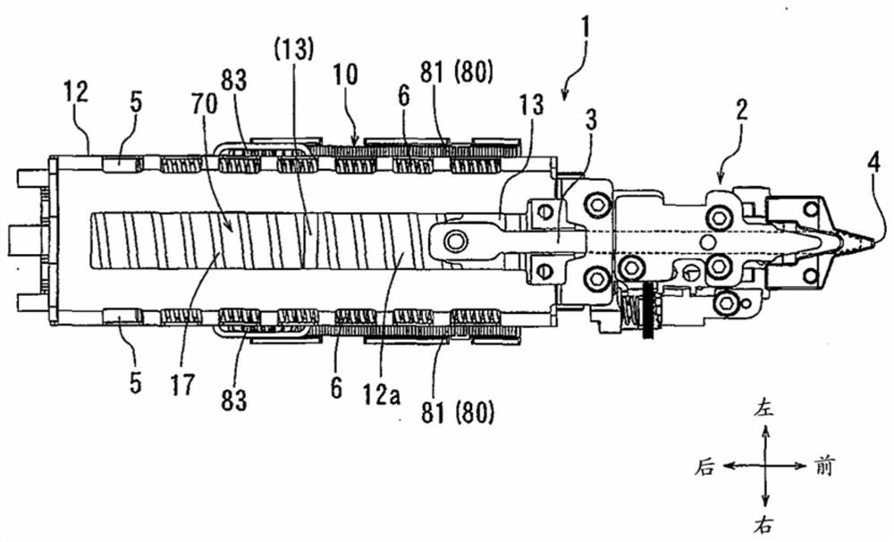
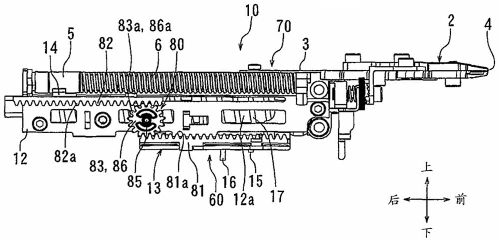
drive tool

A technology for driving tools and drivers, applied in manufacturing tools, nailing tools, nailing tools, etc., can solve problems such as large impact, reduced durability of rack and pinion mechanisms, and dampers in drivers.

Active Publication Date: 2021-07-13
MAKITA CORP
View PDF7 Cites 0 Cited by
  • Summary
  • Abstract
  • Description
  • Claims
  • Application Information

AI Technical Summary

Problems solved by technology

Therefore, a large impact is applied to the meshing teeth of the rack and pinion, which reduces the durability of the rack and pinion mechanism
Since in the prior art disclosed in the above-mentioned patent documents, no damper is provided for the driver, the above defects are particularly obvious

Method used


Image

  • drive tool
  • drive tool
  • drive tool

Examples


Embodiment Construction

[0051] When and with Figure 1 The detailed description set forth below is, when considered, a description of exemplary embodiments of the invention and is not intended to be limiting and / or to represent the only embodiments in which the invention may be practiced. The term "exemplary" is used throughout this specification to mean "serving as an example, instance or illustration" and should not be construed as preferred or advantageous over other exemplary embodiments. The detailed description includes specific details in order to provide a thorough understanding of the exemplary embodiments of the invention. It will be apparent to those skilled in the art that the exemplary embodiments of the invention may be practiced without these specific details. In some instances, well-known structures, components and / or devices are shown in block diagram form in order to avoid obscuring important aspects of the example implementations presented herein.

[0052] In the following, refer...


PUM


Abstract

In the rack and pinion mechanism (80), a driving side gear (83) and a driven side gear (86) are provided so as to be coaxially rotatable relative to each other within a predetermined angular range. Due to this structure, the moment when the driver (3) reaches the forward end position and contacts the forward end damper (19) deviates from the moment when the counterweight device (5) reaches the retracted end position and contacts the moving end damper (7) In the case of the case, through the relative rotation of the gear (83) and the gear (86), no excessive external force will be applied to the meshing teeth (81a) and the meshing teeth (82a). Therefore, due to this structure, the durability of the rack and pinion mechanism (80) absorbing the end impact by elastic deformation is improved.

Description

[0001] Cross References to Related Applications [0002] This application claims the benefit of Japanese Patent Application Serial No. 2015-217785 filed on November 5, 2015 and Japanese Patent Application Serial No. 2016-185457 filed on September 23, 2016, the entire contents of both applications Incorporated herein by reference. technical field [0003] The present invention generally relates to a driving tool, such as a rechargeable nailer. Background technique [0004] Generally, in a driving tool such as a nailer mainly used for joining wood or plasterboard, the biasing force of a compression spring or an air cylinder is used as the driving force. In the former case, the electric motor is used as the drive source by which the driver (for striking the nail, etc.) is retracted to its inactive position against the spring force (the driving force for striking the nail). In this specification, the driving tool in the former case may be called an electric driving tool, and t...

Claims


Application Information

Patent Timeline
Patent Type & Authority Patents(China)
IPC IPC(8): B25C7/00B25C1/06
CPCB25C1/06B25C7/00
Inventor 宫下勋宫田贤一
Owner MAKITA CORP
Why Eureka
Try Eureka