
Novel bridge equipment

A technology for bridges and equipment, applied in the field of new bridge equipment, can solve the problems of shortened service life, short power supply line settings, inability to meet the power supply connection requirements of multiple groups of maintenance equipment, etc., to prevent damage and improve service life.

Active Publication Date: 2017-07-28
JIANGSU XIYI HIGH NEW DISTRICT TECH DEV CO LTD
View PDF7 Cites 1 Cited by
  • Summary
  • Abstract
  • Description
  • Claims
  • Application Information

AI Technical Summary

Problems solved by technology

[0002] Electrified maintenance equipment is often used in the bridge maintenance process. However, in some bridge constructions, there are fewer preset power supply sockets, which cannot meet the power supply and connection requirements for multiple sets of maintenance equipment at the same time. In addition, the existing bridge power supply sockets are all fixed settings. When the construction maintenance site is far away from the power supply base, the power supply connection cannot be completed due to the relatively short power supply line setting of the electrified maintenance equipment. In the past, when encountering similar problems, one or more terminal boards are generally used to lengthen the connection. To achieve the purpose of plugging power supply for electrified maintenance equipment. However, after multiple terminal boards are connected, the power supply line has a certain length, which is extremely inconvenient when rewinding. service life

Method used


Image

  • Novel bridge equipment
  • Novel bridge equipment
  • Novel bridge equipment

Examples


Embodiment Construction

[0020] All features disclosed in this specification, or steps in all methods or processes disclosed, may be combined in any manner, except for mutually exclusive features and / or steps.

[0021] Any feature disclosed in this specification (including any appended claims, abstract and drawings), unless expressly stated otherwise, may be replaced by alternative features which are equivalent or serve a similar purpose. That is, unless expressly stated otherwise, each feature is one example only of a series of equivalent or similar features.

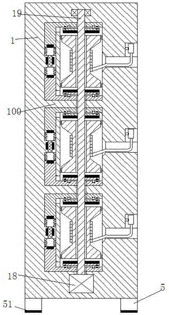
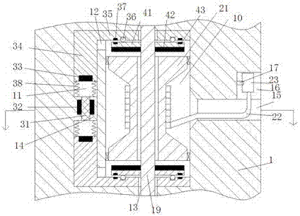
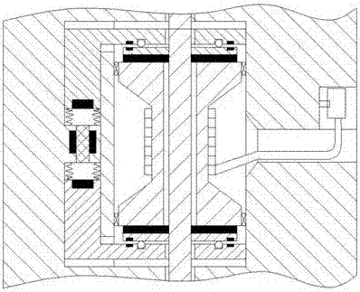
[0022] Such as Figure 1-5 As shown, a new type of bridge equipment of the present invention includes a base body 1, in which a plurality of power supply devices are divided up and down by a flat plate 100, and each power supply device includes a cavity 10 arranged in the base body 1 And the hole groove 15 that is arranged in the right end wall of the cavity 10, the upper end of the hole groove 15 is provided with a mounting groove 16, and th...


PUM


Abstract

Novel bridge equipment comprises a base body. The base body is internally provided with a plurality of power supply devices in an up and down dividing manner through a flat plate. Each power supply device comprises a containing cavity formed in the base body and a hole groove formed in the right end wall of the containing cavity, wherein the upper end of the hole groove is provided with an installation groove, a clamping frame is fixedly arranged on the wall of the installation groove, a winding roll is rotationally arranged in the containing cavity, a cable is arranged on the winding roll, a socket is fixedly arranged on the tail of the cable and clamped to the clamping frame, and locking parts are arranged on the outer sides of the hole groove and the installation groove.

Description

technical field [0001] The invention relates to the technical field of bridge facilities, in particular to a novel bridge equipment. Background technique [0002] Electrified maintenance equipment is often used in the bridge maintenance process. However, in some bridge constructions, there are fewer preset power supply sockets, which cannot meet the power supply and connection requirements for multiple sets of maintenance equipment at the same time. In addition, the existing bridge power supply sockets are all fixed settings. When the construction maintenance site is far away from the power supply base, the power supply connection cannot be completed due to the relatively short power supply line setting of the electrified maintenance equipment. In the past, when encountering similar problems, one or more terminal boards are generally used to lengthen the connection. To achieve the purpose of plugging power supply for electrified maintenance equipment. However, after multiple...

Claims


Application Information

Patent Timeline
Patent Type & Authority Applications(China)
IPC IPC(8): B65H75/44
CPCB65H75/4486B65H2701/34
Inventor 项侠风
Owner JIANGSU XIYI HIGH NEW DISTRICT TECH DEV CO LTD
Learn More