Laterally located device

A technology of lateral positioning and positioning parts, which is applied in the direction of connecting components, pins, mechanical equipment, etc.

Inactive Publication Date: 2017-07-28
FIVETECH TECH INC
View PDF11 Cites 4 Cited by
  • Summary
  • Abstract
  • Description
  • Claims
  • Application Information

AI Technical Summary

Problems solved by technology

[0003] However, if it is used to combine two objects that are perpendicular to each other, for example, the fixed surface of the first object is in the X direction, and the fixed surface of the second object is in the Y direction perpendicular to the X direction, the above-mentioned fixed components will not be able to align vertically. Objects in two directions are assembled, screwed or snapped

Method used


Image

  • Laterally located device
  • Laterally located device
  • Laterally located device

Examples


Embodiment Construction

[0147] In order to fully understand the purpose, features and effects of the present invention, now through the following specific embodiments, and in conjunction with the accompanying drawings, the present invention will be further described in detail, as follows:

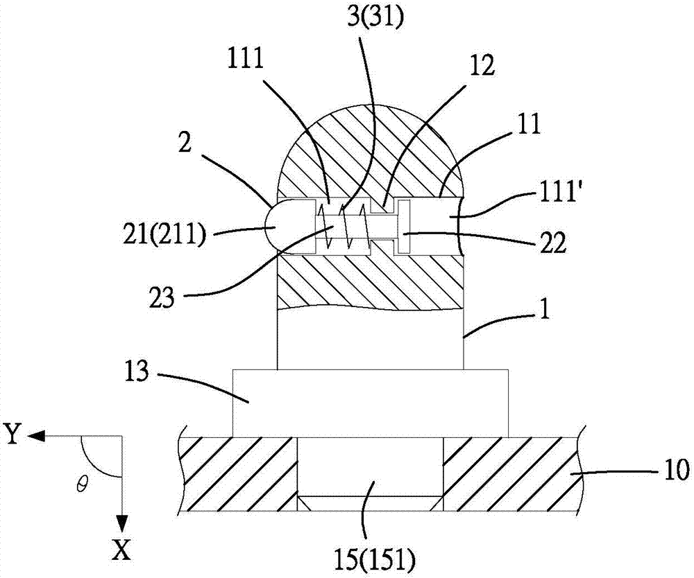
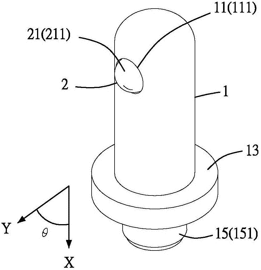
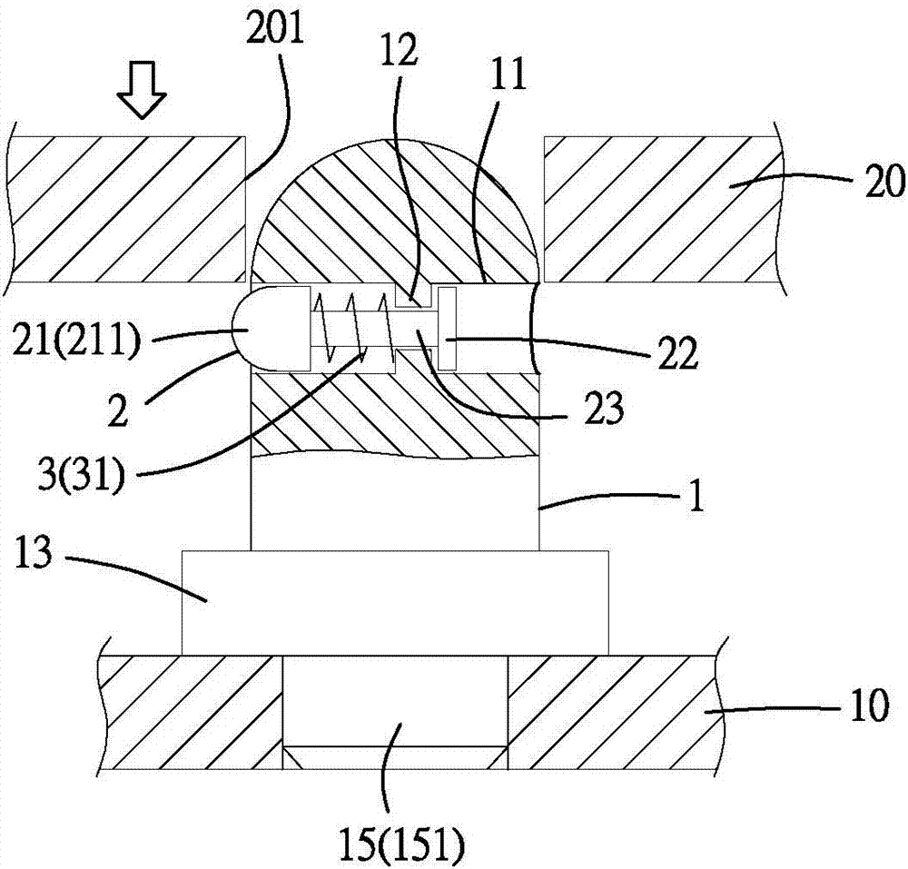
[0148] refer to figure 1 and figure 2 or Figure 6 and Figure 7 As shown, it is shown as a lateral positioning device of the present invention, which is used to be combined with a first object 10 (such as a casing, a frame, a plate or a circuit board, etc.), and buckled laterally or obliquely on a second object. The lateral positioning device of the object 20 (such as other casings, frames, plates or circuit boards, etc.), its preferred embodiment includes a body 1, and a positioning member 2 that is movably arranged on the body 1, wherein : the body 1 can be specifically implemented as a cylinder (rod), a cylinder, a rod, a block, a sheet (such as Figure 6 and Figure 7shown), cutaway body, bent body, pol...


PUM


Abstract

The invention provides a laterally located device for being combined at a first object and laterally buckled or intervened at a second object to link the two objects and separate the two objects at any time. The laterally located device includes a body portion combined at the first object in a first direction and including a bore in a second direction having an angle with the first direction, a limiting portion being in the bore; and a locating piece passing through the bore, limited by the limiting portion and moving in the second direction, the locating piece having a buckling portion positioned at a first side of the limiting portion to enable the bucking portion to be buckled or intervened at a second object, a stop portion positioned at a second side of the limiting portion, and a neck portion connected to the buckling position and the stop portion and passing through the limiting portion.

Description

technical field [0001] The invention relates to a lateral positioning device, in particular to a lateral positioning device which is combined with a first object and can be fastened laterally to a second object. Background technique [0002] Currently used to connect two parallel plates, a fixed component can be used to form the connection. The fixed component usually adopts the technology of screw locking. The specific implementation method includes a screw and a sleeve to form a fixed component; wherein, the screw One end has a force-receiving part, the force-receiving part is provided with a screwdriver slot, and the other end has a screw rod connected with the force-receiving part; the sleeve fits on the screw rod of the screw so that the screw can move in the sleeve. In this way, the fixed component can be combined on the first object (such as a circuit board) by using one end of the sleeve, and the screw rod of the screw can pass through one end of the sleeve and corre...

Claims


Application Information

Patent Timeline
Patent Type & Authority Applications(China)
IPC IPC(8): F16B13/10
CPCF16B13/04F16B13/10
Inventor 王鼎瑞
Owner FIVETECH TECH INC
Why Eureka
Try Eureka