Dance barre device and dance training room

A training room and dance technology, applied in sports accessories, stilts, gymnastics equipment, etc., can solve the problem that the dance bar cannot be used by different users or the same user in different usage states.

Inactive Publication Date: 2017-08-04
YANCHENG INST OF TECH
View PDF4 Cites 1 Cited by
  • Summary
  • Abstract
  • Description
  • Claims
  • Application Information

AI Technical Summary

Problems solved by technology

[0003] The present invention aims to provide a dance bar device to solve the problem that the dance

Method used


Image

  • Dance barre device and dance training room
  • Dance barre device and dance training room
  • Dance barre device and dance training room

Examples


Embodiment 1

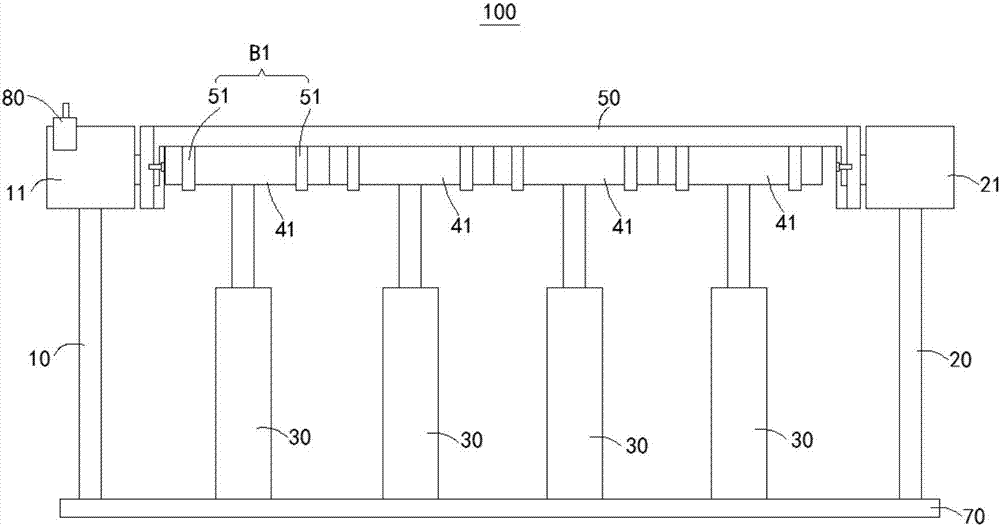
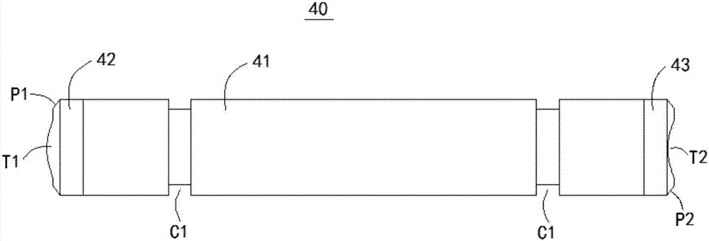
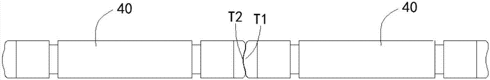
[0044] figure 1 It is a structural schematic diagram of the dance bar device 100 in the first embodiment of the present invention. Please refer to figure 1, the dance bar device 100 in this embodiment includes a first upright pole 10 and a second upright pole 20 that are spaced apart from each other. Between the first vertical rod 10 and the second vertical rod 20 are provided a plurality of telescopic cylinders 30 spaced apart from each other. The telescopic ends of the telescopic cylinders 30 face upward and are fixedly connected with a sub-rod 40 along the horizontal direction. Each sub-rod 40 is configured to be able to move vertically to a position coaxial with each other or a position staggered from each other under the drive of the corresponding telescopic cylinder 30 . The dance bar device 100 also includes elastically stretchable pads 50, and the two ends of the pads 50 are respectively rotatably connected to the end of the first pole 10 and the end of the second po...

Embodiment 2

[0057] Figure 7 It is a schematic structural diagram of the dance training room 010 in the second embodiment of the present invention. See Figure 7 , the dance training room 010 in this embodiment includes a surrounding wall, a ground G1 and the dance bar device 100 in the first embodiment. The lower ends of the first vertical pole 10, the second vertical pole 20 and each telescopic cylinder 30 are pre-embedded and fixed on the ground G1.

[0058] To sum up, the dance training room 010 in this embodiment has the beneficial effect of being able to adapt to different users or different usage states of the same user because it is equipped with the dance bar device 100 in the first embodiment.


PUM


Abstract

The invention relates to the field of sports facilities, and provides a dance barre device and a dance training room. The dance barre device and the dance training room aim at solving the problem that an existing dance barre cannot be suitable for different users or the different using states of a same user. The dance barre device comprises a first standing rod, a second standing rod and a plurality of stretchable cylinders, wherein first standing rod, the second standing rod and the stretchable cylinders are mutually arranged at intervals, and all the stretchable cylinders are fixedly connected with sub-rods in the horizontal direction respectively. All the sub-rods can be driven by the corresponding stretchable cylinders to move to be at the coaxial position or the staggered position in the vertical direction. The dance barre device also comprises a filler strip capable of elastically being stretched and shortened, and the two ends of the filler strip are rotationally connected to the end of the first standing rod and the end of the second standing rod respectively, and can rotate around the rotating axis which is parallel to the axes of the sub-rods. A plurality of connecting ring sets are fixedly arranged in the length direction of the filler strip at intervals; all the sub-rods are correspondingly and rotationally matched in the corresponding connecting ring sets respectively. The dance barre device has the advantage that the dance barre device can be suitable for different users or the different using states of a same user.

Description

technical field [0001] The invention relates to the field of sports equipment, in particular to a dance bar device and a dance training room. Background technique [0002] The dance bar is an auxiliary tool in the dance body training process, for example, it can be used for leg presses. The dance bar in the prior art has the problem that it cannot be adapted to different users or different usage states of the same user at the same time. Contents of the invention [0003] The present invention aims to provide a dancing bar device to solve the problem that the dancing bar in the prior art cannot be applied to different users or different usage states of the same user. [0004] Another object of the present invention is to provide a dance training room equipped with the above dance bar device. [0005] Embodiments of the present invention are achieved like this: [0006] A dance bar device, which includes a first upright pole and a second upright pole which are spaced apar...

Claims


Application Information

Patent Timeline
IPC IPC(8): A63B26/00
CPCA63B26/00A63B2225/093
Inventor 田媛
Owner YANCHENG INST OF TECH
Why Eureka
Try Eureka