Electric resistance welding integrated equipment for fuel tank filler

A fuel filler and resistance welding technology, which is applied in the field of resistance welding, can solve problems such as low automation, affecting product quality, and weldment deformation, and achieve the effects of improving automation, improving product quality, and increasing welding strength

Pending Publication Date: 2021-04-02
江苏耀坤液压股份有限公司
View PDF0 Cites 0 Cited by
  • Summary
  • Abstract
  • Description
  • Claims
  • Application Information

AI Technical Summary

Problems solved by technology

[0003] The disadvantages of the existing resistance welding equipment are: the structure design of the electrode head is limited, and only one welding spot can be completed at a time. Not only is the efficiency low, but also the clamping device is fixed and the degree of automation is low.
In addition, due to the pressure during the welding process, it is easy to cause deformation of the weldment, which affects product quality

Method used


Image

  • Electric resistance welding integrated equipment for fuel tank filler
  • Electric resistance welding integrated equipment for fuel tank filler
  • Electric resistance welding integrated equipment for fuel tank filler

Examples


Embodiment approach

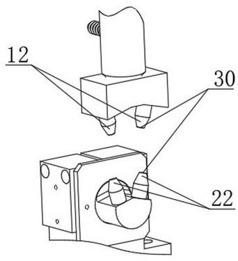
[0033] Such as figure 2 As shown, it is the second embodiment of the welding head assembly of this embodiment. The first electrode and the second electrode each include two electrode heads, which are respectively two B upper electrode heads 12 and two B lower electrode heads 22. The two B upper electrode heads 12 and the two B lower electrode heads 22 are matched respectively, and the welding process of two welding spots is completed at the same time each time.

[0034] The two B upper electrode heads 12 are spaced apart along the circumferential direction, and correspondingly, the two B lower electrode heads 22 are spaced apart along the circumferential direction. The above-mentioned interval distribution distance can be adaptively designed according to the shape of the welding surface of the position to be welded on the workpiece and the location of the welding spots to meet the maximum number of welding spot welding under the condition that the number of rotations is as sm...


PUM


Abstract

The invention relates to electric resistance welding integrated equipment for a fuel tank filler. The equipment comprises a welding head assembly and a clamping assembly, wherein the welding head assembly comprises a first electrode and a second electrode matched with the first electrode; each of the first electrode and the second electrode comprises at least one electrode tip, and welding machining of at least one welding spot is completed each time; the clamping assembly comprises a rotary clamping jaw, and the rotary clamping jaw is connected with the driving mechanism and is used for clamping and adjusting the workpiece in the horizontal direction and the vertical direction and driving the workpiece to rotate. The working face contours of the electrode tip of the first electrode and the electrode tip of the second electrode are matched with each other, and the first electrode and the second electrode are tightly attached to the workpiece from two sides of the welding position during working, so that the working face is attached to the contour of the corresponding to-be-welded face on the workpiece. The structural design of the electrode tip is optimized, and it is convenient tomatch the workpiece with the electrode tip by matching with a function that the clamping assembly can adjust the position of the workpiece randomly, so that the machining efficiency is improved whilethe degree of automation is improved.

Description

technical field [0001] The invention relates to the technical field of resistance welding, in particular to an integrated resistance welding equipment for fuel tank filling ports. Background technique [0002] Resistance welding refers to the method of using the resistance heat generated by the current passing through the weldment and the contact as the heat source to locally heat the weldment and simultaneously pressurize it for welding. When welding, no filler metal is required for high productivity. [0003] The disadvantages of the existing resistance welding equipment are: the structure design of the electrode head is limited, and only one welding spot can be completed at a time. Not only is the efficiency low, but also the clamping device is fixed and the degree of automation is low. In addition, due to the pressure during the welding process, the weldment is easily deformed, which affects the product quality. Contents of the invention [0004] The invention provid...

Claims


Application Information

Patent Timeline
Patent Type & Authority Applications(China)
IPC IPC(8): B23K11/11B23K11/30B23K11/36
CPCB23K11/11B23K11/30B23K11/36
Inventor 范凯许海烽杜经纶徐逸诚
Owner 江苏耀坤液压股份有限公司
Why Eureka
Try Eureka