Clogged container dredging tool for cleaning

A container and tooling technology, which is applied in the field of dredging the blockage of complexed iron desulfurization containers, to achieve the effects of ensuring sealing, saving costs, and ensuring stability

Active Publication Date: 2022-07-05
CHINA PETROLEUM & CHEM CORP +1
View PDF7 Cites 0 Cited by
  • Summary
  • Abstract
  • Description
  • Claims
  • Application Information

AI Technical Summary

Problems solved by technology

[0005] The technical purpose of the present invention is to provide a cleaning tool for dredging a clogged container that can effectively unclog the clogged situation without emptying the reaction container in view of the clogged situation of the above-mentioned container and the technical deficiencies in the existing emptying and dredging operation

Method used


Image

  • Clogged container dredging tool for cleaning
  • Clogged container dredging tool for cleaning

Examples


Embodiment 1

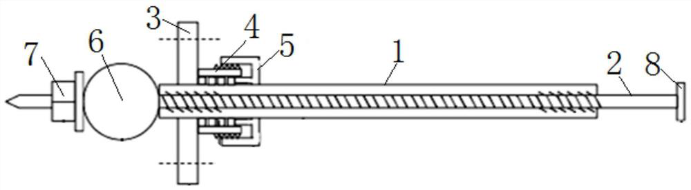
[0026] see figure 1 As shown, the present invention includes a sleeve 1 and a rod 2 .

[0027]The outer diameter of the sleeve 1 is smaller than the inner diameter of the clogging part of the clogging container to be cleaned (because the clogging part of the clogging container is usually a circular pipe structure or a through-hole structure, for the convenience of description, hereinafter referred to as the clogging pipe). The outer circumference of the sleeve 1 is sheathed with a flange 3 in a movable assembly structure, which can ensure that the sleeve 1 can achieve axial displacement or circumferential rotation in the flange 3; the flange 3 is matched to the method of blocking the end of the pipe. Flange structure, the flange 3 on the sleeve 1 can be connected to the flange structure at the end of the blocking pipe through a plurality of locking bolts. A dynamic sealing structure is arranged between the flange plate 3 and the sleeve 1, and the dynamic sealing structure is ...

Embodiment 2

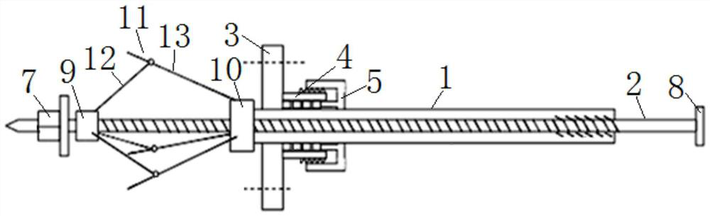
[0036] see figure 2 As shown, the present invention includes a sleeve 1 and a rod 2 .

[0037] The outer diameter of the sleeve 1 is smaller than the inner diameter of the clogging part of the clogging container to be cleaned (because the clogging part of the clogging container is usually a circular pipe structure or a through-hole structure, for the convenience of description, hereinafter referred to as the clogging pipe). The outer circumference of the sleeve 1 is sheathed with a flange 3 in a movable assembly structure, which can ensure that the sleeve 1 can achieve axial displacement or circumferential rotation in the flange 3; the flange 3 is matched to the method of blocking the end of the pipe. Flange structure, the flange 3 on the sleeve 1 can be connected to the flange structure at the end of the blocking pipe through a plurality of locking bolts. A dynamic sealing structure is arranged between the flange plate 3 and the sleeve 1, and the dynamic sealing structure i...

Embodiment 3

[0046] The present invention includes a sleeve and a rod.

[0047] The outer diameter of the sleeve is smaller than the inner diameter of the clogging part of the clogging container to be cleaned (because the clogging part of the clogging container is usually a circular pipe structure or a through-hole structure, for the convenience of description, hereinafter referred to as the clogging pipe). The outer circumference of the sleeve is sleeved with a flange plate in a movable assembly structure, which can ensure that the sleeve can realize axial displacement or circumferential rotation in the flange plate; the flange plate is matched with the flange structure blocking the end of the pipe, and the sleeve The upper flange can be butted with the flange structure at the end of the blocking pipe through a plurality of locking bolts. A dynamic sealing structure is arranged between the flange plate and the sleeve, and the dynamic sealing structure is located on the rear side of the fl...


PUM


Abstract

The invention discloses a cleaning tool for dredging a plugged container. The cleaning tool has a sleeve that can be butted on the plugged container, and a cleaning tool which is inserted into the sleeve and extends out of the sleeve at the front end and the rear end respectively. A long rod, the front end of the long rod can extend into the blocking container, and a deformation mechanism that can radially deform with the axial displacement of the long rod is connected between the front end of the long rod and the sleeve , the deformation mechanism is used to clear the blockage in the blockage container. The present invention can effectively clear the blockage in the container without emptying the container. Of course, this kind of clearing operation is also applicable to the emptying container, and has the characteristics of convenience, high efficiency, labor saving, cost saving and the like.

Description

technical field [0001] The invention relates to a dredging tool, in particular to a cleaning tool for dredging a clogging container, which is especially suitable for dredging the clogging state of a complex iron desulfurization container. Background technique [0002] Containers are used for holding materials, especially flowing media - such as liquids or gases, etc. Large containers are usually provided with a discharge port for discharging the materials contained inside, and some large containers - especially chemical reaction vessels are usually provided with internal The discharge port for the circulating flow of the contained materials. The discharge port on the container is usually located at the bottom of the container, and an outwardly extending pipe is usually connected to the discharge port. During long-term use, the substances (or impurities) in the materials contained in the container will form deposits at the bottom of the container. Based on the drainage chara...

Claims


Application Information

Patent Timeline
Patent Type & Authority Patents(China)
IPC IPC(8): B08B9/087
CPCB08B9/087
Inventor 谭东林熊重寒孟献金罗广祥高利聂凌唐洋陈伟朱毅卓银川文刚李关俊乔林曾慧罗毅周永淳
Owner CHINA PETROLEUM & CHEM CORP
Why Eureka
Try Eureka