
A method and system for checking concatenated polar code encoding

A coding method and polar code technology are applied in the direction of using linear codes for error correction/detection, using block codes for error correction/detection, data representation error detection/correction, etc., which can solve the problems of large implementation complexity, high cost, Problems such as complex verification relationship

Active Publication Date: 2019-06-11
HUAZHONG UNIV OF SCI & TECH
View PDF4 Cites 0 Cited by
  • Summary
  • Abstract
  • Description
  • Claims
  • Application Information

AI Technical Summary

Problems solved by technology

In order to achieve good error correction performance of the calibrating concatenated polar code, it is necessary to optimize the construction of the verification relationship, that is, to optimize and determine which information bits are verified by each parity bit, which leads to a very complicated verification relationship.
For some relatively long codes, the verification relationship is so complex that it is difficult to express it in text. Even if these verification relations are stored in electronic files, a large amount of storage space will be consumed, resulting in great implementation complexity and high cost.

Method used


Image

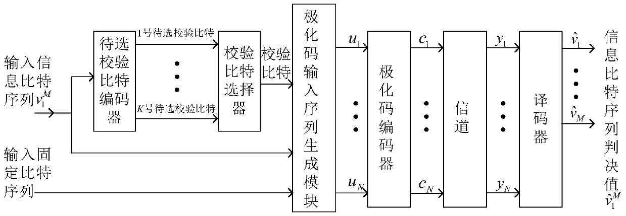
  • A method and system for checking concatenated polar code encoding
  • A method and system for checking concatenated polar code encoding
  • A method and system for checking concatenated polar code encoding

Examples


Embodiment 1

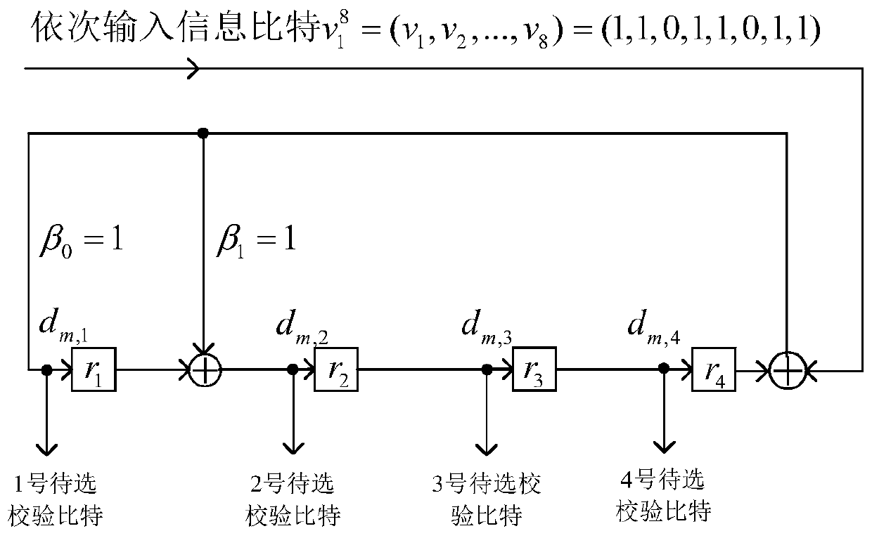
[0107] Embodiment 1: CRC-4 division circuit is used to implement the candidate check bit encoder;

[0108] Let the CRC-4 division circuit generator polynomial be G(X)=X 4 +X+1, then β in the division circuit 0 = 1, β 1 = 1, β 4 =1, the to-be-selected parity bit encoder implemented by the CRC-4 division circuit is such as image 3 Shown.

[0109] Input information bit sequence When encoding, the bit v 1 To v 8 Input the parity bit encoder to be selected one by one;

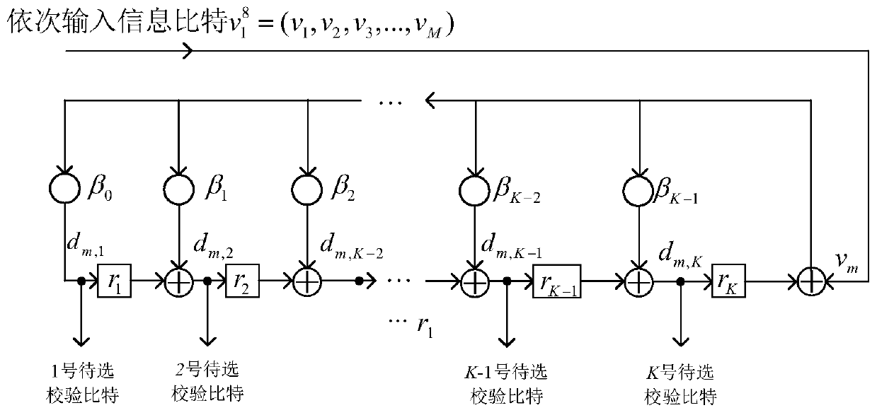
[0110] Each input information bit v m (1≤m≤8), output 4 to-be-selected check bits, serially numbered from 1 to 4, to be selected as d m,j , Where j is the sequence number of the check bit to be selected, 1≤j≤4.

[0111] Set check bit sequence u P The sequence of the candidate check bit sequence number corresponding to each check bit in is The working process of the to-be-selected parity bit encoder and parity bit selector is shown in Table 1:

[0112] Table 1 The working process list of the candidate parity bit encoder and...

Embodiment 2

[0116] Embodiment 2: A generator matrix is ​​used to implement a candidate parity bit encoder;

[0117] In this embodiment, M=8, K=4; the candidate parity bit encoder generates matrix G′ M×K The dimension is M×K=8×4, generating matrix G′ 8×4 as follows:

[0118]

[0119] The input information bit sequence is Set check bit sequence u P The sequence of the candidate check bit sequence number corresponding to each check bit in

[0120] Since the first parity bit u 9 Next to the third information bit u 7 After that, the third information bit u 7 When inputting, you need to select the first parity bit u to output 9 , In the coding formula (d m,1 ,d m,2 ,...,d m,K )=(v 1 ,v 2 ,...,v m ,0,0,...,0)G′ M×K As an example, the 4 candidate check bits obtained from the matrix generated by the candidate check bit encoder are: (d 3,1 ,d 3,2 ,d 3,3 ,d 3,4 )=(v 1 ,v 2 ,v 3 ,0,0,0,0,0)G′ 8×4 =(1,0,1,1). Since the first parity bit u 9 The corresponding candidate check bit sequence number is t 1...

Embodiment 3

[0122] Embodiment 3: adopting multi-output convolutional code encoding to realize the candidate parity bit encoder;

[0123] This embodiment adopts the multi-output convolutional coding to realize the candidate check bit encoder such as Figure 4 Shown; input information bit sequence

[0124] To be selected check bit encoder input bit v in sequence when encoding 1 To v 8 ; Check bit sequence u P The sequence of the candidate check bit sequence number corresponding to each check bit in The working process of the to-be-selected parity bit encoder and parity bit selector is shown in Table 2.

[0125] Table 2 The working process list of the candidate parity bit encoder and parity bit selector of embodiment 3

[0126]

[0127]

[0128] The working process and principle of the check bit selector in this embodiment are explained as follows: because the first check bit u 9 Next to the third information bit u 7 After that, after the third information bit is input, the check bit u is selected ...


PUM


Abstract

The invention discloses a check cascading polarization code encoding method and system. The method comprises the following steps: encoding an input information bit sequence by using a to-be-selected check bit encoder, outputting a plurality of to-be-selected check bits for each input information bit, and selecting a check bit from these to-be-selected check bits; arranging all information bits according to an input sequence, arranging the selected check bit behind the corresponding current information bit, and inserting a fixed bit in the sequence to form a polarization code input sequence; performing polarization code encoding on the polarization code input sequence to obtain a check cascading polarization code codeword; and decoding the check cascading polarization code codeword by using an improved SCL decoding algorithm. The invention further discloses an expression method of the check cascading polarization code. By adoption of the method and system provided by the invention, the check relationship is simplified under the same error correction performance, and thus the check cascading polarization code has a succinct expression method; and when the check relationship is stored in an electronic mode, the storage space is better saved.

Description

Technical field [0001] The present invention belongs to the technical field of error correction encoding and decoding, and more specifically, relates to a method and system for verifying cascaded polarization code encoding and decoding. Background technique [0002] As a new type of coding scheme close to Shannon’s limit, polarization coding has a low complexity of encoding and decoding algorithms, which is conducive to engineering realization. The simulation results show that the polarization code SCL (Successive Cancellation List) decoding algorithm is effective With a lower complexity O(L·Nlog(N)) (L is the number of paths, N is the code length), the error correction capability can reach the error correction capability of the maximum likelihood decoder. However, for the limited code length polarization code using the SCL decoding algorithm, the error correction performance still has a large gap with the Shannon limit, and this gap cannot be compensated by increasing the number...

Claims


Application Information

Patent Timeline
Patent Type & Authority Patents(China)
IPC IPC(8): H03M13/13
CPCH03M13/13
Inventor 屈代明王涛江涛
Owner HUAZHONG UNIV OF SCI & TECH
Learn More