Check cascading polarization code encoding method and system
A coding method and polar code technology, which are applied in the direction of using linear codes for error correction/detection, using block codes for error correction/detection, data representation error detection/correction, etc., which can solve the problem of large implementation complexity and consumption of storage space , high cost and other issues
- Summary
- Abstract
- Description
- Claims
- Application Information
AI Technical Summary
Problems solved by technology
Method used
Image
Examples
Embodiment 1
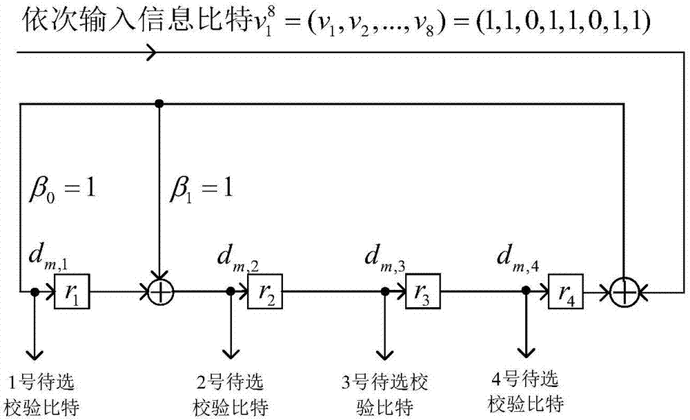
[0107] Embodiment 1: adopt the CRC-4 division circuit to realize the check bit encoder to be selected;
[0108] Let the CRC-4 division circuit generator polynomial be G(X)=X 4 +X+1, then β in the division circuit 0 =1,β 1 =1,β 4 =1, the candidate check bit encoder that adopts CRC-4 division circuit to realize is as image 3 shown.
[0109] input information bit sequence When encoding, the bit v 1 to v 8 Input the check bit encoder to be selected in turn;
[0110] Each input information bit v m (1≤m≤8), output 4 check bits to be selected, numbered 1 to 4 in sequence, and the check bits to be selected are denoted as d m,j , where j is the number of check bits to be selected, 1≤j≤4.
[0111] Set check bit sequence u P The sequence formed by the number of check bits to be selected corresponding to each check bit in is The working process of the check bit encoder to be selected and the check bit selector is shown in Table 1:
[0112] Table 1. Check bit encoder to be ...
Embodiment 2
[0116] Embodiment 2: using a generating matrix to realize a check bit encoder to be selected;
[0117] In this embodiment, M=8, K=4; the candidate check bit encoder generates matrix G' M×K Dimensions are M×K=8×4, generating matrix G′ 8×4 as follows:
[0118]
[0119] The input information bit sequence is Set check bit sequence u P A sequence of check bit numbers to be selected corresponding to each check bit in
[0120] Since the first parity bit u 9 next to the third information bit u 7 After that, therefore the third information bit u 7 When inputting, you need to choose to output the first parity bit u 9 , to encode the formula (d m,1 , d m,2 ,...,d m,K )=(v 1 ,v 2 ,...,v m ,0,0,...,0)G′ M×K For example, according to the generation matrix of the check bit encoder to be selected, the 4 check bits to be selected are: (d 3,1 , d 3,2 , d 3,3 , d 3,4 )=(v 1 ,v 2 ,v 3 ,0,0,0,0,0)G′ 8×4 =(1,0,1,1). Since the first parity bit u 9 The corresponding chec...
Embodiment 3
[0122] Embodiment 3: using multi-output convolutional code encoding to realize the check bit encoder to be selected;
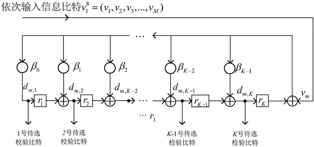
[0123] In this embodiment, the candidate check bit encoder implemented by multi-output convolutional coding is as follows: Figure 4 shown; the input information bit sequence
[0124] Input the bit v sequentially when encoding the check bit encoder to be selected 1 to v 8 ; check bit sequence u P A sequence of check bit numbers to be selected corresponding to each check bit in Table 2 shows the working process of the check bit encoder to be selected and the check bit selector.
[0125] Table 2 Check bit encoder to be selected and check bit selector working process list of embodiment 3
[0126]
[0127]
[0128] The working process and principle of the parity bit selector in this embodiment are explained as follows: because the first parity bit u 9 next to the third information bit u 7 After that, after the third information bit is input, the ou...
PUM
 Abstract
Description
Claims
Application Information
 - R&D
- Intellectual Property
- Life Sciences
- Materials
- Tech Scout
- Unparalleled Data Quality
- Higher Quality Content
- 60% Fewer Hallucinations
Browse by: Latest US Patents, China's latest patents, Technical Efficacy Thesaurus, Application Domain, Technology Topic, Popular Technical Reports.
© 2025 PatSnap. All rights reserved.Legal|Privacy policy|Modern Slavery Act Transparency Statement|Sitemap|About US| Contact US: help@patsnap.com


