
Ventilation pipe cleaning device

A technology of cleaning device and ventilation duct, applied in the field of ventilation, can solve the problems of difficult metal sheath, inability to clean multiple reciprocating and bent ventilation ducts, and difficulty in cleaning ventilation ducts.

Pending Publication Date: 2017-08-11
BEIJING JINMAO GREEN BUILDING TECH CO LTD
View PDF9 Cites 0 Cited by
  • Summary
  • Abstract
  • Description
  • Claims
  • Application Information

AI Technical Summary

Problems solved by technology

The metal sheath is difficult to bend back and forth, so it is difficult to clean the ventilation ducts with many twists and turns, and the cleaning of the ventilation ducts will not become a consideration during architectural design, which makes the combination of flexible shaft and metal sheath in the prior art It is impossible to clean the multiple reciprocating bending ventilation ducts in the prior art

Method used


Image

  • Ventilation pipe cleaning device
  • Ventilation pipe cleaning device

Examples


Embodiment Construction

[0028] In order to enable those skilled in the art to better understand the technical solutions of the present invention, the present invention will be further described in detail below in conjunction with the accompanying drawings.

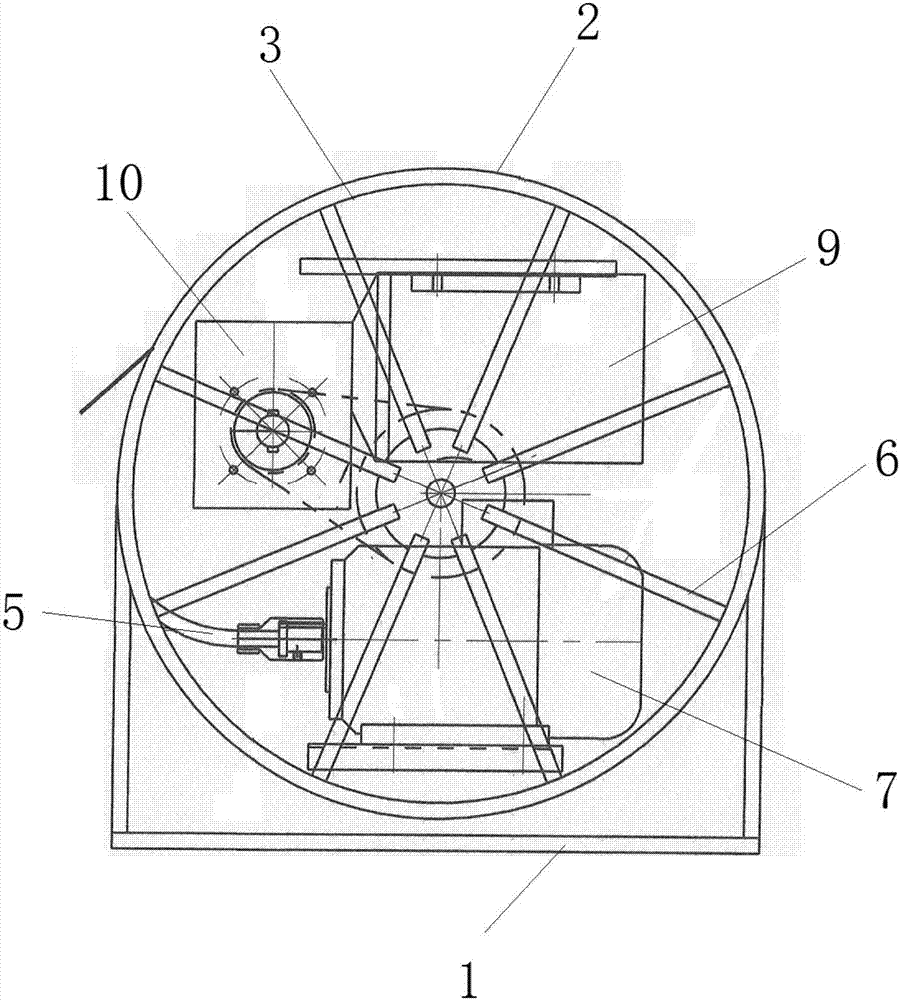
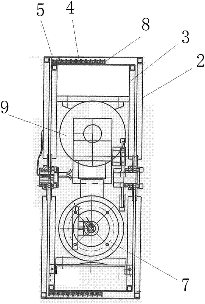
[0029] like Figure 1-2 As shown, a ventilation duct cleaning device provided by an embodiment of the present invention includes a base frame 1, an outer cylinder body 2, an inner cylinder body 3, a flexible shaft 5 and a flexible shaft drive unit 7, and the outer cylinder body 2 is connected to the base on the frame 1; the inner cylinder 3 is sleeved in the outer cylinder 2, which is rotatably connected to the base frame 1, and the outer wall of the inner cylinder 3 is provided with a spiral accommodation groove 4; the flexible shaft 5 Accommodated in the spiral accommodation groove 4, its cleaning end protrudes from the outer side of the outer cylinder 2 through the shaft outlet on the outer cylinder 2, and its driving end passes through the sh...


PUM


Abstract

The invention discloses a ventilation pipe cleaning device. The ventilation pipe cleaning device comprises a base frame, an outer cylinder, an inner cylinder, a soft shaft and a soft shaft driving unit; the outer cylinder is connected to the base frame; the inner cylinder is sleeved in the outer cylinder, and is rotationally connected to the base frame; a spiral accommodating tank is formed in the outer wall of the inner cylinder; the soft shaft is accommodated in the spiral accommodating tank, a cleaning end thereof extends to the outer side of the outer cylinder through a shaft outlet of the outer cylinder, and a driving end thereof extends to the inner side of the inner cylinder through an opening on the inner cylinder; and the soft shaft driving unit is used for driving the driving end of the soft shaft. In the ventilation pipe cleaning device, the soft shaft positioned out of a ventilation pipe is limited in the spiral accommodating tank between the outer cylinder and the inner cylinder; the soft shaft extending in the ventilation pipe is a naked shaft without an outer sleeve protection mechanism; and the soft shaft can achieve infinite reciprocating bending without influencing the rotating effect, so that various ventilation pipe structures bent in a reciprocating manner in the prior art can be cleaned.

Description

technical field [0001] The invention relates to ventilation technology, in particular to a ventilation duct cleaning device. Background technique [0002] During the use of the ventilation duct, the duct wall is easy to absorb dust, so it is better to clean the ventilation duct regularly to maintain the high-efficiency operation of the ventilation duct. The ventilation duct cleaning device in the prior art includes a flexible shaft with a metal sheath on the flexible shaft, and a cleaning brush is arranged at one end of the flexible shaft. When cleaning, the flexible shaft and the metal sheath are inserted into the interior of the ventilation duct, and then The outside of the ventilation duct drives the other end of the flexible shaft to rotate at a high speed, so that the cleaning brush rotates at a high speed to clean the duct wall of the ventilation duct. [0003] With the gradual improvement of people's living standards and the continuous advancement of science and tech...

Claims


Application Information

Patent Timeline
IPC IPC(8): B08B9/045B08B9/043
CPCB08B9/0436B08B9/045B08B2209/04
Inventor 李俊高峰武振兴王福乔宗里刚杨冰
Owner BEIJING JINMAO GREEN BUILDING TECH CO LTD
Learn More