
A bulk material flow measuring device

A flow measurement device and bulk material technology, which is applied in the direction of measurement device, measurement flow/mass flow, liquid/fluid solid measurement, etc., can solve problems such as measurement failure, resistance increase, and influence on measurement results, so as to improve reliability and avoid The effect of hanging and measuring accurately

Active Publication Date: 2019-05-17
HENAN UNIVERSITY OF TECHNOLOGY
View PDF5 Cites 2 Cited by
  • Summary
  • Abstract
  • Description
  • Claims
  • Application Information

AI Technical Summary

Problems solved by technology

However, this device has the following problems: ①If there are flexible impurities such as rope ends and cloth pieces in the material, they will be entangled on the blades; The flow velocity of each point above is not exactly the same, which affects the measurement accuracy; ③ If the material flows in a circular pipe (not mentioned in the patent), some unknown factors will cause the material to rotate around the axis of the pipe, which directly affects the measurement result ;④The bearing supporting the blade is surrounded by the material, and the long-term operation will increase the resistance or even stop due to the infiltration of dust, making the measurement invalid
The above problems have an impact on the measurement accuracy and reliability of the device, and are also one of the factors that have not been popularized and applied so far.

Method used


Image

  • A bulk material flow measuring device
  • A bulk material flow measuring device
  • A bulk material flow measuring device

Examples


Embodiment Construction

[0021] The present invention will be further described below in conjunction with embodiment (accompanying drawing):

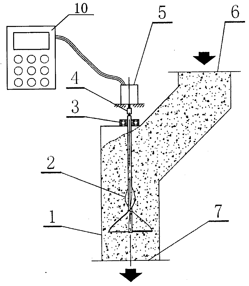
[0022] like image 3 As shown, the bulk material flow measurement device of the present invention includes a barrel 1, which is a vertically arranged cylinder with a polygonal cross-section (see Figure 5 ), the upper part of the cylinder body is provided with a feed port 6 extending to the side and connected to the discharge port of the silo, and the lower end is a discharge port 7; in the vertical cavity of the barrel 1, the The bearing 3 above the top surface of the barrel 1 is installed with a conical helix 2 in a suspended manner, and the upper end of the mandrel of the conical helix 2 is connected with the photoelectric rotary encoder 5 through a flexible coupling 4; The spiral body 2 is composed of two same equal-pitch variable-diameter helical blades 9 symmetrically welded on the mandrel 8. Each blade is wound around the mandrel for half a circle. And...


PUM


Abstract

A scattered material flow measurement device includes a machine barrel; the machine barrel is a vertical barrel having a polygonal cross section; a feeding opening which is connected to a discharging opening of a material bin and extends in the upper side direction is arranged on the upper part of the barrel, and a discharging opening is formed in the lower end of the barrel; a cone-shaped spiral body is hanged in a vertical chamber of the machine barrel through a bearing arranged above a top surface of the machine barrel; an upper end of a core shaft of the cone-shaped spiral body is connected to a photoelectric rotary encoder through a flexible coupling; the coned spiral body includes two pitch-equal diameter-variable spiral blades which are symmetrically welded on the core shaft; and each blade winds the core shaft half a round, a surface bus of each spiral blade is a linear positive spiral surface perpendicular to an axis, each spiral blade is of a structure the width of which is increasing gradually from top to bottom, and a half pitch of each spiral blade is equal to the lowest diameter of the blade.

Description

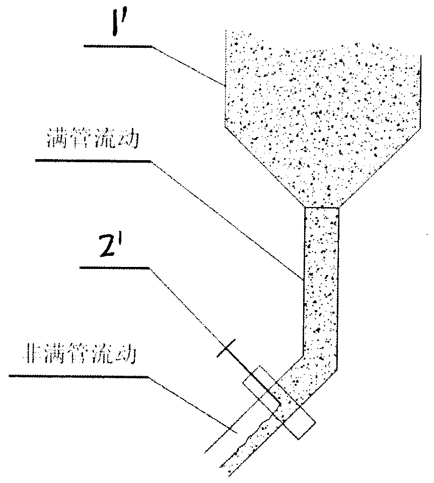
technical field [0001] The invention relates to a bulk material (bulk material, bulk) flow metering device, which is used for continuously measuring the flow rate and measuring the total amount of the bulk material during the flow process of the bulk material. It belongs to the technical field of bulk material measurement. Background technique [0002] During the processing, transportation and batching of bulk materials (bulk materials), it is often necessary to continuously measure the flowing materials. According to the filling state of the material in the pipeline, it can be divided into two forms: full pipe flow and non-full pipe flow. like figure 1 As shown, the flow from the outlet of the silo to the throttle gate is full pipe flow, and the flow after the throttle gate is partly full pipe flow. It is relatively easy to realize the measurement of materials under the flow state of a partially filled pipe. At present, equipment such as punching plate flowmeters, nuclea...

Claims


Application Information

Patent Timeline
Patent Type & Authority Patents(China)
IPC IPC(8): G01F1/10
CPCG01F1/103
Inventor 毛广卿王争艳关二旗张帅飞
Owner HENAN UNIVERSITY OF TECHNOLOGY
Learn More