
Self-balance type air floating display device

A display device, self-balancing technology, applied in display devices, special decorative structures, decorative arts, etc., can solve the problems of complex structure, waste of power resources, etc., and achieve the effect of increasing visual effects

Inactive Publication Date: 2017-08-15
HEFEI PANSHI AUTOMATION TECH
View PDF7 Cites 2 Cited by
  • Summary
  • Abstract
  • Description
  • Claims
  • Application Information

AI Technical Summary

Problems solved by technology

The mechanical matrix pendant of the present invention drives the decorative blocks forward, backward or stops at different positions, and realizes the change of various three-dimensional graphic effects through the automatic control of the control part. It can display text, graphics, changing animations, etc., and can be displayed synchronously with audio and video. The exhibition site has a strong three-dimensional effect, but although it also has the effect of aerial display, the structure is complicated and wastes power resources

Method used


Image

  • Self-balance type air floating display device
  • Self-balance type air floating display device

Examples


Embodiment 1

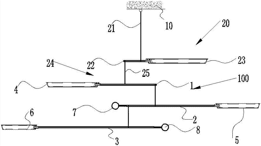
[0020] Such as figure 1 As shown, a schematic structural diagram of a self-balancing floating display device in the air in Embodiment 1, in this embodiment, includes a support frame 10, and several color wheel units 20 are fixed on the support frame 10, and the color wheel unit 20 includes one end hanging The first flexible connector 21 on the support frame 10, the first cantilever rod 22 connected to the other end of the first flexible connector 21, the first color wheel 23 fixed on the end of the first cantilever rod 22 and the fixed The suspension unit 24 at the other end of the first cantilever rod 22, the connection points between the suspension unit 24 and the first color wheel 23 and the first cantilever rod 22 are respectively located at the connection between the first flexible connector 21 and the first cantilever rod 22 point, and the first cantilever rod 22 maintains horizontal balance;

[0021] The geometric dynamic principle adopted at this time is: the distance...

Embodiment 2

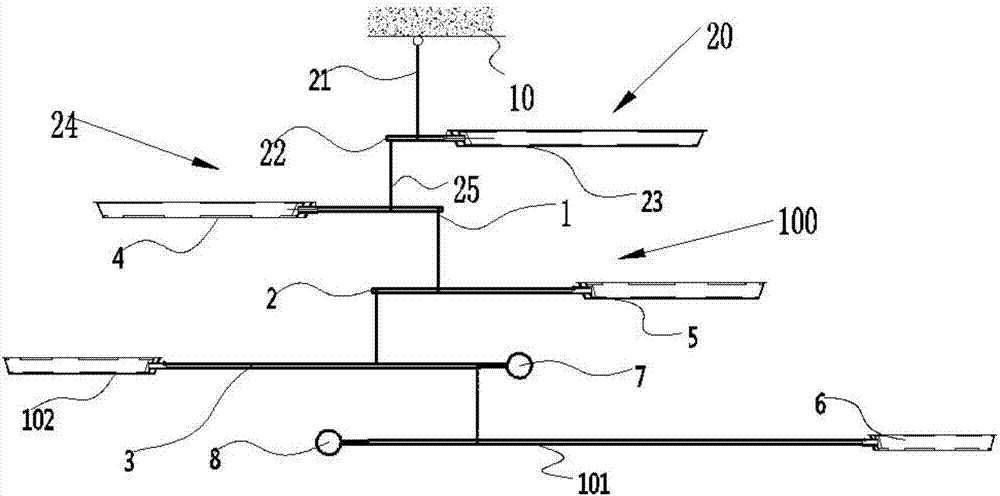
[0026] Such as figure 2 As shown, a schematic structural diagram of a self-balancing floating display device in the air in Embodiment 2, in this embodiment, includes a support frame 10, and several color wheel units 20 are fixed on the support frame 10, and the color wheel unit 20 includes one end hanging The first flexible connector 21 on the support frame 10, the first cantilever rod 22 connected to the other end of the first flexible connector 21, the first color wheel 23 fixed on the end of the first cantilever rod 22 and the fixed The suspension unit 24 at the other end of the first cantilever rod 22, the connection points between the suspension unit 24 and the first color wheel 23 and the first cantilever rod 22 are respectively located at the connection between the first flexible connector 21 and the first cantilever rod 22 point, and the first cantilever rod 22 maintains horizontal balance;

[0027] The geometric dynamic principle adopted at this time is: the distanc...


PUM


Abstract

The invention provides a self-balance type air floating display device, and belongs to the display device technical field; the self-balance type air floating display device comprises a support; the support is fixedly provided with a plurality of color disc units; the color disc unit comprises a first flexible connector with one end hung on the support, a first cantilever rod connected with the other end of the first flexible connector, a first color disc fixed on the first cantilever rod end portion, and a suspension unit fixed on the other end of the first cantilever rod; the connecting points between the suspension unit and the first color disc and the first cantilever rod are respectively located on two sides of the connecting point between the first flexible connector and the first cantilever rod, and the first cantilever rod keeps horizontal balance. The self-balance type air floating display device is simple in structure, easy to mount, can combine structures to realize machinery balance, and can use airflow to realize air floating movements without using outer force, thus providing beautiful visual sense effect for people.

Description

technical field [0001] The invention belongs to the technical field of display devices, in particular to a self-balancing display device floating in the air. Background technique [0002] Dynamic art is dynamic art, which emerged in Europe in the 19th century. Dynamic art can be cut and combined with rods, wires, plates, and sheet materials to form geometric shapes such as lines, triangles, rectangles, and circles. When combined, they are suspended in the air or placed on the table to present a beautiful artistic effect. For any material with uniform density, such as a rod or wire with a uniform cross-section, its center of gravity is located at the center of its length, and For example, a plate or sheet with uniform thickness, the center of gravity is located in the center of its area. When these components are balanced at the center, the center of the airflow driving force coincides with it. In this case, the airflow can only push the components and not It cannot be tilte...

Claims


Application Information

Patent Timeline
Patent Type & Authority Applications(China)
IPC IPC(8): G09F19/02B44C5/00
CPCG09F19/02B44C5/00
Inventor 陈友明舒玉恒胡勇启
Owner HEFEI PANSHI AUTOMATION TECH
Learn More