Eureka AIR delivers breakthrough ideas for toughest innovation challenges, trusted by R&D personnel around the world.

Foam clamping equipment

A foam and equipment technology, which is applied in the field of foam clamping equipment, can solve the problems of foam deformation, damage to the overall appearance of the workpiece, easy to produce deviation, etc., and achieve the effect of high production efficiency.

Pending Publication Date: 2017-08-22
SUZHOU DALIKE AUTOMATION TECH
View PDF6 Cites 2 Cited by
  • Summary
  • Abstract
  • Description
  • Claims
  • Application Information

AI Technical Summary

Problems solved by technology

[0002] At present, when removing the foam from the foam board and installing it on the workpiece, manual operations are mostly used. During the process of taking the foam, it is easy to cause deformation of the foam, and it is easy to cause misalignment when it is installed on the workpiece. , destroying the overall beauty of the workpiece, for this reason, we have developed a cylinder to drive the slider to translate left and right; the jaw cylinder can drive the jaws to open and pick up the foam; the slide cylinder can drive the connecting seat to move down, In this way, the sucker assembly can be moved down, and the foam can be sucked under the action of the motor; the motor can drive the movable frame to rotate, so as to realize the rotation of the foam.

Method used


Image

  • Foam clamping equipment
  • Foam clamping equipment

Examples


Embodiment Construction

[0013] The present invention will be further described in detail below in conjunction with the accompanying drawings and specific embodiments.

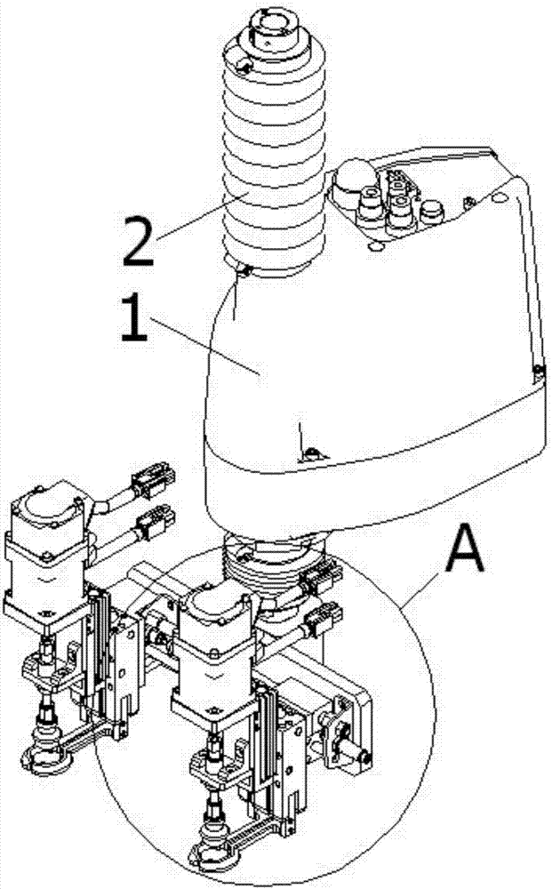
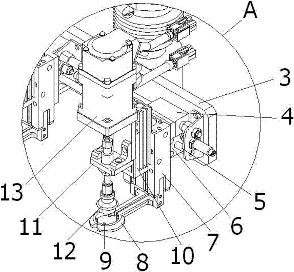
[0014] attached Figure 1-2 It is the clamping foam equipment according to the present invention; it includes a mechanical arm 1; the front part of the mechanical arm 1 is provided with a rotating shaft 2; the lower part of the rotating shaft 2 is provided with a movable frame 3; the movable frame 3 can rotate around the rotating shaft 2 The front end of the movable frame 3 is provided with a rodless assembly 4 and a slide bar 5; the slide bar 5 is provided with a slider 6, and the slide block 6 is connected with the rodless assembly 4; the rodless assembly 4 is driven by a cylinder The slider 6 can be translated left and right; the front end of the slider 6 is provided with a vertical jaw cylinder 7; the jaw cylinder 7 is provided with a jaw 8, and the inner wall of the jaw 8 is provided with a plurality of protrusions 9. The jaw cy...


PUM


Abstract

The invention discloses foam clamping equipment which comprises a mechanical arm. The front portion of the mechanical arm is provided with a rotary shaft. The lower portion of the rotary shaft is provided with a mobile rack which can rotate around the rotary shaft and is provided with a slide block. The slide block can move left and right. The front end of the slide block is provided with a vertical clamping claw cylinder. A clamping claw is arranged below the clamping claw cylinder, and the inner wall of the clamping claw is provided with a plurality of protrusions. The clamping claw cylinder can drive the clamping claw to be opened and then closed to clamp foam. The front end of the clamping claw cylinder is provided with a vertical slide table cylinder which can vertically move on the clamping claw cylinder and is provided with a suction disc assembly. The suction disc assembly can suck the foam. The foam clamping equipment is high in production efficiency and can completely take the foam off a foam plate.

Description

technical field [0001] The invention relates to a foam clamping device which has high production efficiency and can completely remove the foam from a foam board. Background technique [0002] At present, when removing the foam from the foam board and installing it on the workpiece, manual operations are mostly used. During the process of taking the foam, it is easy to cause deformation of the foam, and it is easy to cause misalignment when it is installed on the workpiece. , destroying the overall beauty of the workpiece, for this reason, we have developed a cylinder to drive the slider to translate left and right; the jaw cylinder can drive the jaws to open and pick up the foam; the slide cylinder can drive the connecting seat to move down, In this way, the sucker assembly can be moved down, and the foam can be sucked under the action of the motor; the movable frame can be driven to rotate by the motor, so as to realize the foam gripping equipment for the rotation of the fo...

Claims


Application Information

Patent Timeline
IPC IPC(8): B65G47/91
CPCB65G47/914
Inventor 丁慎平
Owner SUZHOU DALIKE AUTOMATION TECH
Why Eureka
Eureka Blog
Learn More