
Device and method of controlling kitchen appliance

A technology of a control device and a control method, applied in the field of kitchen appliances, can solve the problems of high product failure rate, induction failure, complicated use, etc., and achieve the effect of avoiding unrecognized voice, good use effect, and convenient voice control.

Pending Publication Date: 2017-08-25
GUANGDONG TONZE ELECTRIC CO LTD
View PDF0 Cites 3 Cited by
  • Summary
  • Abstract
  • Description
  • Claims
  • Application Information

AI Technical Summary

Problems solved by technology

At present, the existing kitchen appliances in the market are either single-function or multi-function; for a long time, most of the kitchen appliances we use are knob-type or button-type operations. Due to technical reasons, the mechanical buttons sometimes have empty buttons. Or button top dead phenomenon, due to technical reasons, touch-sensitive buttons often have induction failure or insensitivity, resulting in a high failure rate of products and inconvenience to users
Knob-type or push-button-operated kitchen appliances can meet people's requirements for simple functional operations; but for products with many functions, there are many different cooking materials, and the time required is also different. The entire setting is more complicated. If all knob or button operations are used, there will be many knobs or buttons to operate, and the use will become very complicated, especially not suitable for those who are elderly, people with poor memory and people who do not know much about cooking knowledge use

Method used


Image

  • Device and method of controlling kitchen appliance
  • Device and method of controlling kitchen appliance
  • Device and method of controlling kitchen appliance

Examples


Embodiment 1

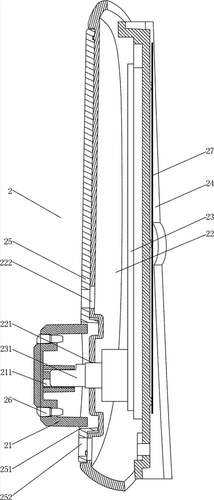
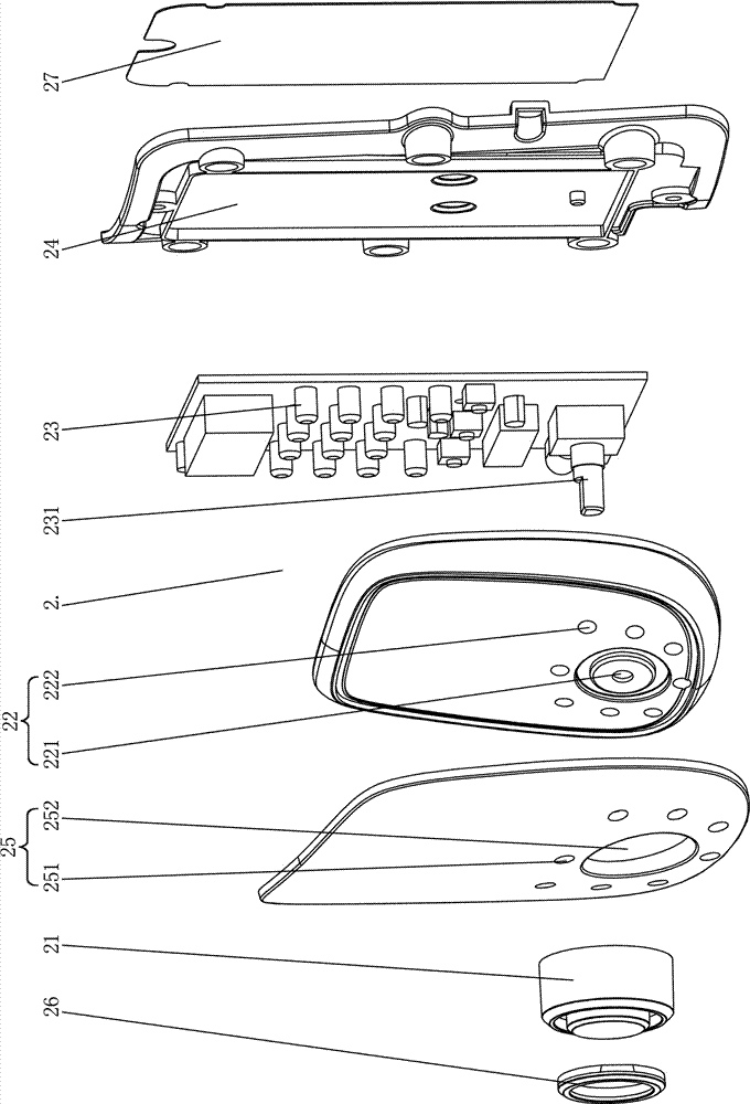
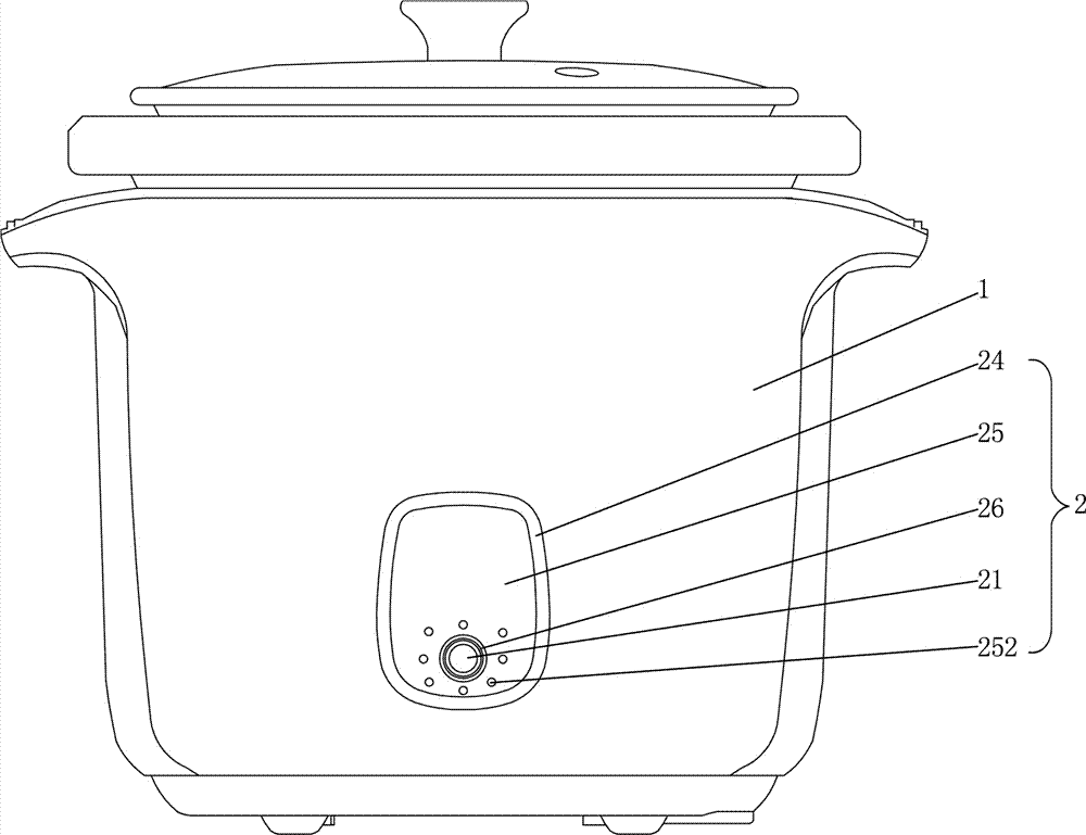
[0047] Such as Figure 1-3 As shown, the control device for kitchen appliances in this embodiment includes a kitchen appliance 1, a control device is provided on the outer wall of the kitchen appliance 1, and the control device includes a knob control mechanism 2, which is arranged in the control device, and the knob control mechanism 2 includes a knob 21, a panel 22, an operation panel 23 and a panel back cover 24, the panel back cover 24 is installed on the outer wall of the kitchen appliance 1, the operation panel 23 is installed on the panel back cover 24, and the operation panel 23 is provided with rotatable buttons 231, the panel 22 has a small hole 221, the bottom of the knob 21 has a slot 211, the rotatable button 231 passes through the small hole 221 and the slot 211 at the bottom of the knob 21 is interlocked, and the knob 21 is installed on the rotatable button 231 superior.

[0048] Eight indicator lights 222 are arranged on the panel 22 , and each indicator light...

Embodiment 2

[0079] The difference between the control device for kitchen appliances in this embodiment and Embodiment 1 is that:

[0080] The number of the indicator lights is seven, and the number of the function flags is seven. The positions of the seven function flags correspond to the positions of the seven indicator lights on the panel. When the knob is rotated to a function flag, the indicator light corresponding to the function flag will light up.

Embodiment 3

[0082] The difference between the control device for kitchen appliances in this embodiment and Embodiment 1 is that:

[0083] The number of the indicator lights is six, and the number of the function flags is six. The positions of the six function flags correspond to the positions of the six indicator lights on the panel. When the knob is rotated to a function flag, the indicator light corresponding to the function flag will light up.


PUM


Abstract

The invention relates to a control device and method for kitchen appliances. The control device of the kitchen appliances includes kitchen appliances, and is characterized in that: the outer wall of the kitchen appliances is provided with a control device, and the control device includes a knob control mechanism. In the device, the knob control mechanism includes a knob, a panel, an operation panel and a panel back cover. The panel back cover is installed on the outer wall of the kitchen appliance, the operation panel is installed on the panel back cover, the operation panel is provided with a rotatable button, and the panel is opened. There is a small hole, and there is a slot at the bottom of the knob, and the rotatable button passes through the small hole and interlocks with the slot at the bottom of the knob, and the knob is installed on the rotatable button. The control device and method for kitchen appliances in the present invention allow users to accurately control kitchen appliances conveniently and quickly, control different functions of kitchen appliances, and at the same time facilitate users to perform voice control, especially the user's unique voice. Typing improves the accuracy of voice manipulation.

Description

technical field [0001] The invention relates to a kitchen appliance, in particular to a control device and method for the kitchen appliance. Background technique [0002] With the progress of society and the continuous development of science and technology, people's requirements for material and cultural living standards are constantly improving, and the performance requirements for kitchen appliances are also getting higher and higher. At present, the existing kitchen appliances in the market are either single-function or multi-function; for a long time, most of the kitchen appliances we use are knob-type or button-type operations. Due to technical reasons, the mechanical buttons sometimes have empty buttons. Or the dead button phenomenon, due to technical reasons, touch-sensitive buttons often have induction failure or insensitivity, resulting in high product failure rates and inconvenience to users. Knob-type or push-button-operated kitchen appliances can meet people's r...

Claims


Application Information

Patent Timeline
IPC IPC(8): G05B19/042G10L15/22
CPCG05B19/0423G05B2219/2643G10L15/22
Inventor 詹文杰黄永喜黄奕莲吕全彬
Owner GUANGDONG TONZE ELECTRIC CO LTD
Learn More