
A sludge flow tester

A tester and silt technology, applied in the field of silt flow tester, can solve the problems of limited growth of soil strength, little guiding significance, silting of plastic drainage boards, etc.

Active Publication Date: 2019-12-20
NANJING TECH UNIV
View PDF8 Cites 0 Cited by
  • Summary
  • Abstract
  • Description
  • Claims
  • Application Information

AI Technical Summary

Problems solved by technology

However, engineering practice shows that after the recently dredged silt foundation is strengthened by the vacuum preloading technology without sand cushion, the strength of the soil body is limited, the effective reinforcement depth of the foundation is small, and the bearing capacity of the foundation is still low.
During the vacuuming process, not only the pore water will flow, but also the dredging and filling sludge particles will flow to a certain extent, and some even enter the board core through the filter membrane. In addition to reducing the permeability coefficient of the soil around the plastic drainage board, it will also cause plastic drainage. The clogging of drainage boards; however, the existing foundation consolidation theory of vacuum preloaded vertical drainage wells only regards pore water as the flow medium, and studies the skeleton formed by soil particles as the deformation medium
This is somewhat different from the actual situation of the project. If this theory is used for the consolidation analysis of dredged silt, it does not have much guiding significance. Therefore, a set of experimental equipment for studying the flow mechanism of dredged silt needs to be developed urgently.

Method used


Image

  • A sludge flow tester
  • A sludge flow tester

Examples


Embodiment Construction

[0018] A specific embodiment of the present invention is given below, and the present invention will be further described in detail through this embodiment. It is necessary to point out that the implementation case is only used to further illustrate the present invention, and the protection scope of the present invention is not limited to this. Some non-essential adjustments and improvements made to the present invention by those skilled in the art still belong to the protection scope of the present invention.

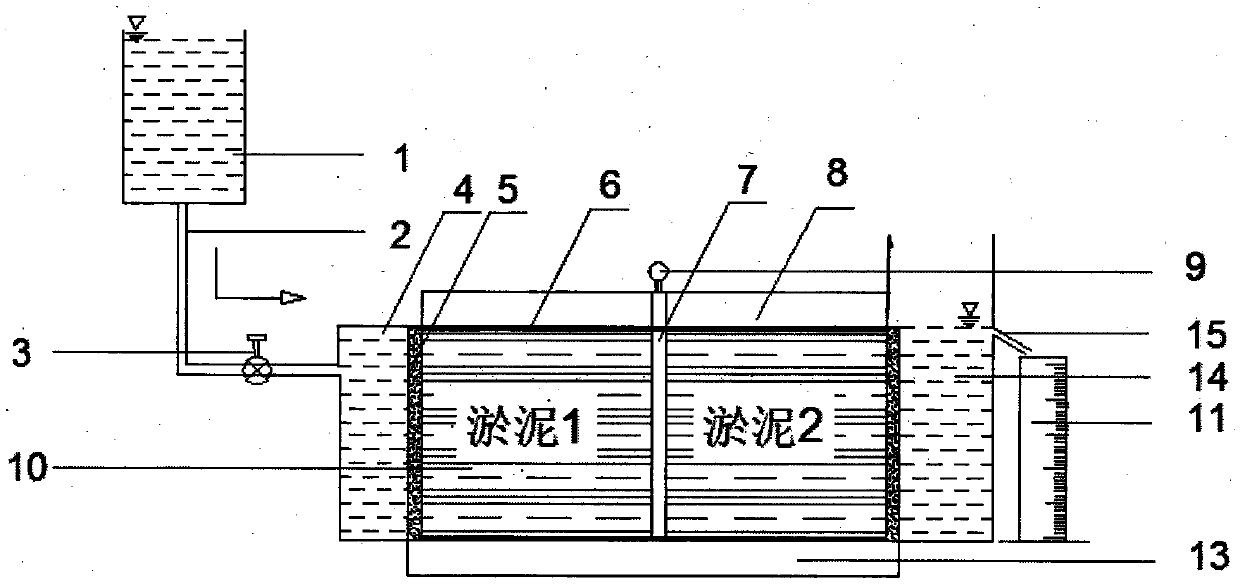
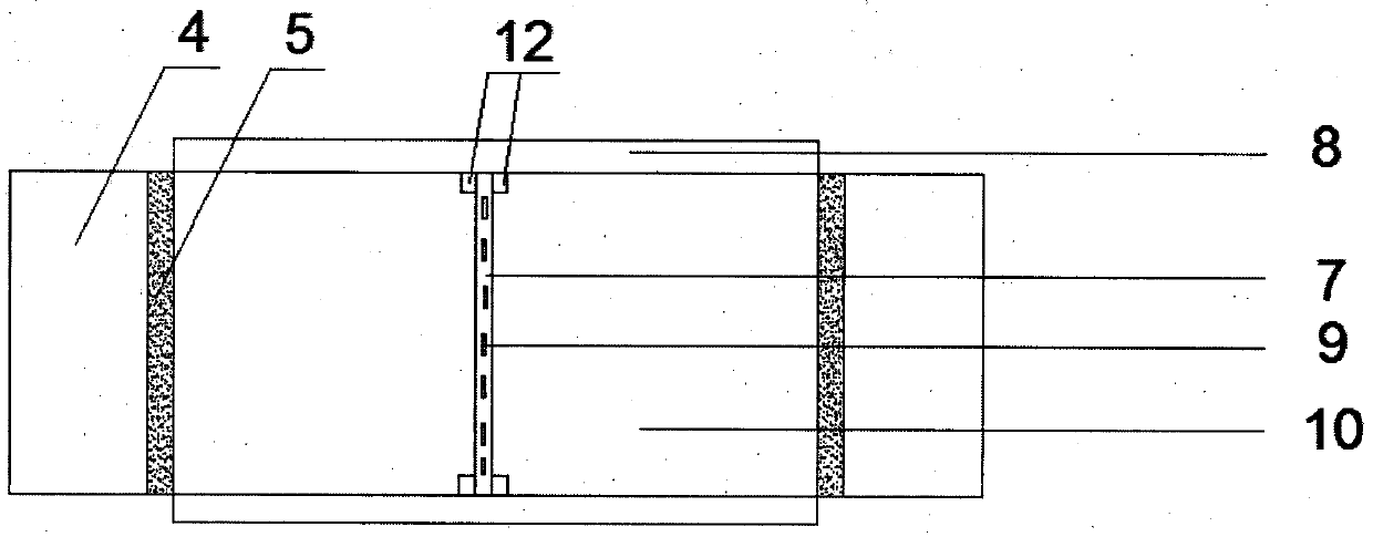
[0019] See Figure 1-2 , A sludge flow tester, comprising a pressure head container 1, the pressure head container 1 and the left water reservoir 4 are connected and sealed by a connecting pipe 2, a water stop valve 3 adjustment switch is provided on the connecting pipe 2, and the left water reservoir 4 There is a permeable stone 5 of a suitable size between the sample chamber 10 and the upper and lower ends of the sample chamber. An upper fixing box 8 and a lower fixing ...


PUM


Abstract

The invention discloses a sludge flowing tester, and belongs to the field of geotechnical engineering. The sludge flowing tester comprises a pressure water head container, a connecting pipe, a water check valve, a water storage device, permeable stones, a partition plate, a sample chamber, a thin baffle piece, a lifting ring buckle, a fixed box, a water outlet, a measuring cylinder and the like. The thin baffle piece is inserted into the sample chamber to separate the soil samples on the two sides of the sample chamber; the thin baffle piece is withdrawn when the water check valve is opened, and the water check valve is closed and the thin baffle piece is inserted into the original position again after a period of time t; the flow change of sludge particles can be obtained by converting through the mass change situation of the soil samples on the two sides after the measurement of a period of time t. According to the sludge flowing tester, the flowing situations of soil particles in the situations of different hydraulic gradients, different void ratios and different effective stresses can also be researched through certain measures, so that the blank of a research direction of a hydraulic fill sludge flowing mechanism is filled. The test scheme is effective and feasible; the test equipment is simple and easy to operate.

Description

Technical field [0001] The invention relates to the field of geotechnical engineering, in particular to the field of dredging engineering, in particular to a silt flow tester. Background technique [0002] With the acceleration of urbanization in developed coastal areas and the continuous expansion of cities, the shortage of coastal land resources has become more and more obvious. Enclosing the sea and building land has also become the most direct and effective way to solve the shortage of land resources. With the government's ban on mountain quarrying and the shortage of sand sources in rivers and other issues, the project had to consider using other materials to reclaim land from the sea. In recent years, dredged silt has been widely used in reclamation projects as a dredging material. It not only solves the problem of dredged silt stacking, but also solves the problem of the source of dredged land filling materials, saves the cost of engineering land and reduces waste The en...

Claims


Application Information

Patent Timeline
Patent Type & Authority Patents(China)
IPC IPC(8): G01N11/02
CPCG01N11/02
Inventor 刘加才史文韬王旭东
Owner NANJING TECH UNIV
Learn More