Laser packaging method and laser packaging equipment

A laser packaging and equipment technology, applied in optics, nonlinear optics, instruments, etc., can solve the problems of semi-finished product accumulation, impact on production capacity, production deviation, etc., and achieve the effect of ensuring packaging efficiency

Active Publication Date: 2019-10-18
BOE TECH GRP CO LTD +1
View PDF7 Cites 0 Cited by
  • Summary
  • Abstract
  • Description
  • Claims
  • Application Information

AI Technical Summary

Problems solved by technology

[0003] In the prior art, when the device to be packaged is in the laser packaging process, it is necessary to manually measure and debug the process route of the spot. First, it is necessary to measure the relevant parameters of the sealing glue from the drawing of the device to be packaged, and input it into the equipment computer to Determine the process route of the light spot (the route of the light spot movement), and then check whether the process route of the light spot is consistent with the printing route of the frame sealant through actual testing (the position of the frame edge is generally deviated from the design position), if not, then It is necessary to manually adjust the process route of the laser spot many times to make it consistent with the printing route of the sealant, and finally ensure the process quality requirements. This process takes 1 to 3 hours
[0004] On the other hand, after the process route of the laser spot has been debugged and applied to mass production, since the frame sealant will have a certain offset during the printing process (the position of each frame edge cannot be guaranteed to be absolutely uniform), the prior art It is necessary to manually check the process route of the laser spot through the equipment monitor in real time. If the process route with the laser spot is found to be inconsistent with the printing route of the sealant, manual correction and debugging are required. This process takes 1 to 2 hours. For a period of time, the equipment cannot correspond to the products completed by the upstream process, which will cause the accumulation of semi-finished products and affect the production capacity

Method used


Image

  • Laser packaging method and laser packaging equipment

Examples


Embodiment Construction

[0029] In order to make the purpose, technical solutions and advantages of this document clearer, the embodiments of this document will be described in detail below in conjunction with the accompanying drawings. It should be noted that, in the case of no conflict, the embodiments in the present application and the features in the embodiments can be combined arbitrarily with each other.

[0030] In the following description, a lot of specific details are set forth in order to fully understand this article, but this article can also be implemented in other ways than described here, therefore, the protection scope of this article is not limited by the specific embodiments disclosed below .

[0031] The laser packaging method and laser packaging equipment of some embodiments herein will be described below with reference to the accompanying drawings.

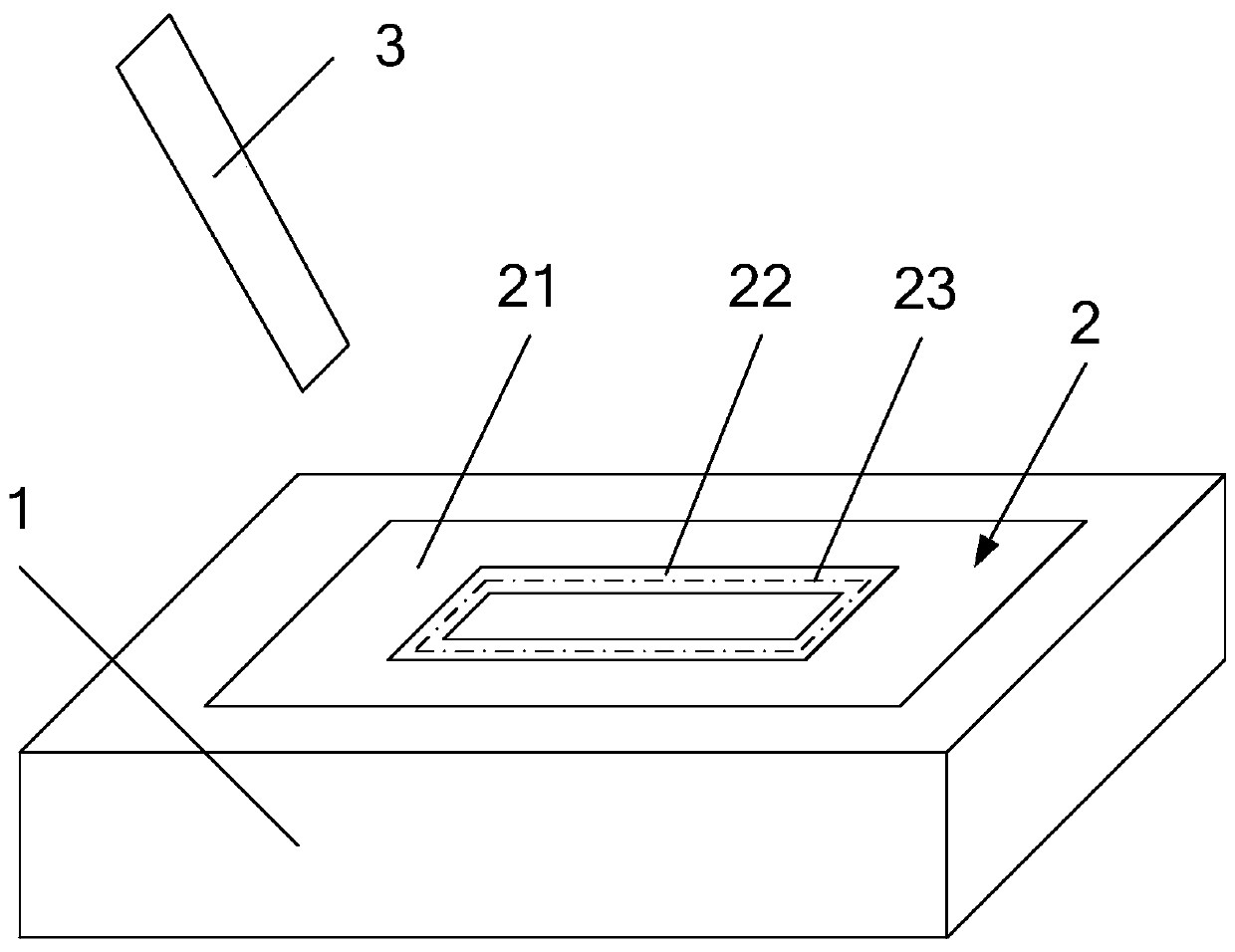
[0032] The laser packaging method provided by the present invention includes:

[0033] The position of the center line of the sea...


PUM


Abstract

The invention discloses a laser encapsulation method and laser encapsulation equipment. The laser encapsulation method comprises the following steps: determining the position of a central line of a frame-sealing adhesive along an encapsulation direction through a central line determination unit to be used as a process route; emitting laser through a laser emission unit and irradiating the laser to an encapsulation region to form a spot; and controlling the centre of the spot to move along the process route, so that the frame-sealing adhesive is encapsulated between two glass substrates, artificial debagging steps of the process route of the spot and a printing route of the frame-sealing adhesive are saved, and the encapsulation efficiency of the encapsulation apparatus is ensured better.

Description

technical field [0001] This article involves but is not limited to liquid crystal display technology, especially a laser packaging method and a laser packaging equipment. Background technique [0002] At present, in the packaging method of liquid crystal display devices (that is: devices to be packaged), laser packaging is to use laser beams on two glass substrates (the sealing glue is set on one glass substrate, and the other glass substrate and the sealing glue are packaged by laser) The sealing glue in between is melted at high temperature to complete the packaging. This process requires that the process route of the laser spot is consistent with the printing route of the sealing glue (that is, the laser spot is irradiated on the frame edge of the sealing glue during the process, and along the frame side movement to achieve encapsulation), so as to ensure that the ratio of the illuminated area is >90%, and the ratio of the illuminated area=(width of the light spot / widt...

Claims


Application Information

Patent Timeline
Patent Type & Authority Patents(China)
IPC IPC(8): G02F1/1341
Inventor 纪鹏
Owner BOE TECH GRP CO LTD
Why Eureka
Try Eureka