
A welding device with stable support

A welding device and a stable technology, applied in the direction of welding equipment, auxiliary equipment, auxiliary welding equipment, etc., can solve the problems of affecting the service life of the welding body, affecting the welding effect, and shaking of the welded parts, so as to increase the efficiency of loading and unloading, reduce Exposure of the welding torch improves processing efficiency

Active Publication Date: 2018-09-18
江门市新会区天健家具有限公司
View PDF5 Cites 0 Cited by
  • Summary
  • Abstract
  • Description
  • Claims
  • Application Information

AI Technical Summary

Problems solved by technology

[0002] Welding is a manufacturing process and art of joining welded parts such as iron or other thermoplastic materials by means of heating, high temperature or high pressure. Usually, when welding small pieces of welded parts, the contact between the welding torch and the welded parts is easy to make the welded parts produce Shaking, thus affecting the welding effect, the existing fixing device is usually installed separately to fix the welded parts first, and then weld the welded parts. After welding, it needs to be disassembled, and it needs to be repeatedly fixed and disassembled Shutting down and starting the welding body is cumbersome and affects the service life of the welding body

Method used


Image

  • A welding device with stable support
  • A welding device with stable support
  • A welding device with stable support

Examples


Embodiment Construction

[0019] All features disclosed in this specification, or steps in all methods or processes disclosed, may be combined in any manner, except for mutually exclusive features and / or steps.

[0020] Any feature disclosed in this specification (including any appended claims, abstract and drawings), unless expressly stated otherwise, may be replaced by alternative features which are equivalent or serve a similar purpose. That is, unless expressly stated otherwise, each feature is one example only of a series of equivalent or similar features.

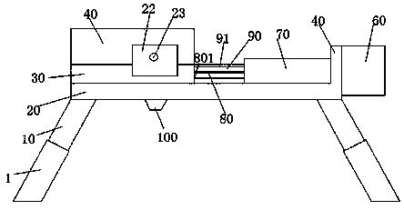
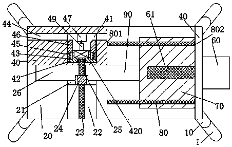
[0021] Such as Figure 1-3 As shown, a welding device with stable support of the present invention includes a support foot 10, a worktable 20 fixed on the upper end of the support foot 10, a positioning plate 30 fixedly installed on the left end of the upper end surface of the workbench 20, and a positioning plate fixed on the left end of the workbench 20. The vertical plate 40 on the right end of the upper end surface of the workbench 20, th...


PUM


Abstract

The invention discloses a welding device capable of supporting stably. The welding device comprises supporting legs, a workbench fixed at the upper ends of the supporting legs, a locating plate fixedly arranged at the left end of the upper end face of the workbench, and a vertical plate fixedly arranged at the right end of the upper end face of the workbench; the supporting legs are obliquely arranged; adjusting sleeves are arranged at the lower ends of the supporting legs in an up-and-down adjusting manner; a position guide column is fixedly arranged between the locating plate and the vertical plate; a sliding plate is slidingly arranged on the position guide column; a sliding groove which extends leftwards and rightwards is formed in the centers of the front and the rear of the locating plate; the upper end and the right end of the sliding groove are opened; a sliding strip is arranged at the left end of the sliding plate; the left end of the sliding strip penetrates into the sliding groove; a tooth-shaped strip is arranged at the upper end face of the sliding strip; the locating plate is located at the rear end of the sliding groove; a welding table is fixedly arranged on the locating plate; a containing groove which extends leftwards and rightwards and is used for containing a welding part is formed in the rear end of the welding table; a vertical sliding groove with the port facing the containing groove is formed in the welding table; a vertical sliding block is arranged in the vertical sliding groove in a front and back sliding manner; a welding machine body is fixedly arranged in the vertical sliding block; and a welding gun is arranged on the welding machine body.

Description

technical field [0001] The invention relates to the field of welding equipment, in particular to a welding device with stable support. Background technique [0002] Welding is a manufacturing process and art of joining welded parts such as iron or other thermoplastic materials by means of heating, high temperature or high pressure. Usually, when welding small pieces of welded parts, the contact between the welding torch and the welded parts is easy to make the welded parts produce Shaking, thus affecting the welding effect, the existing fixing device is usually installed separately to fix the welded parts first, and then weld the welded parts. After welding, it needs to be disassembled, and it needs to be repeatedly fixed and disassembled Turning off and starting the welding body is cumbersome and affects the service life of the welding body. Contents of the invention [0003] The object of the present invention is to provide a welding device with stable support and its u...

Claims


Application Information

Patent Timeline
Patent Type & Authority Patents(China)
IPC IPC(8): B23K37/00B23K37/02B23K37/04
CPCB23K37/00B23K37/02B23K37/0443
Inventor 钟潘霄
Owner 江门市新会区天健家具有限公司
Learn More