
Fixing device for welding of alternating current capacitor terminal

A technology for fixing devices and capacitors, which is applied in the field of capacitors. It can solve problems affecting the welding efficiency of capacitor terminals and the main board, capacitor position offset, and heavy manual operation burden.

Inactive Publication Date: 2022-03-18
铜陵市科峰电子有限责任公司
View PDF0 Cites 0 Cited by
  • Summary
  • Abstract
  • Description
  • Claims
  • Application Information

AI Technical Summary

Problems solved by technology

[0003] Although capacitors are widely used, there are problems in their actual use. The existing capacitors need to be fixed when welding, and this operation is often done manually. Because some capacitors are small in size, they need to be fixed when welding. Clamp the capacitor with tweezers, but this operation is very easy to make the position of the capacitor shift, which affects the efficiency of welding the capacitor terminal and the main board, and you need to wait until it cools down during welding to check whether the welding is firm again with the tweezers. The process is not only inefficient, but also has a large burden of manual operation, which is prone to mistakes

Method used


Image

  • Fixing device for welding of alternating current capacitor terminal
  • Fixing device for welding of alternating current capacitor terminal
  • Fixing device for welding of alternating current capacitor terminal

Examples


Embodiment 1

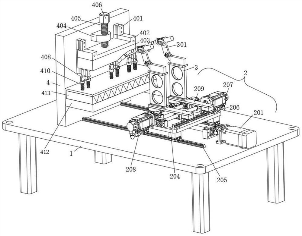
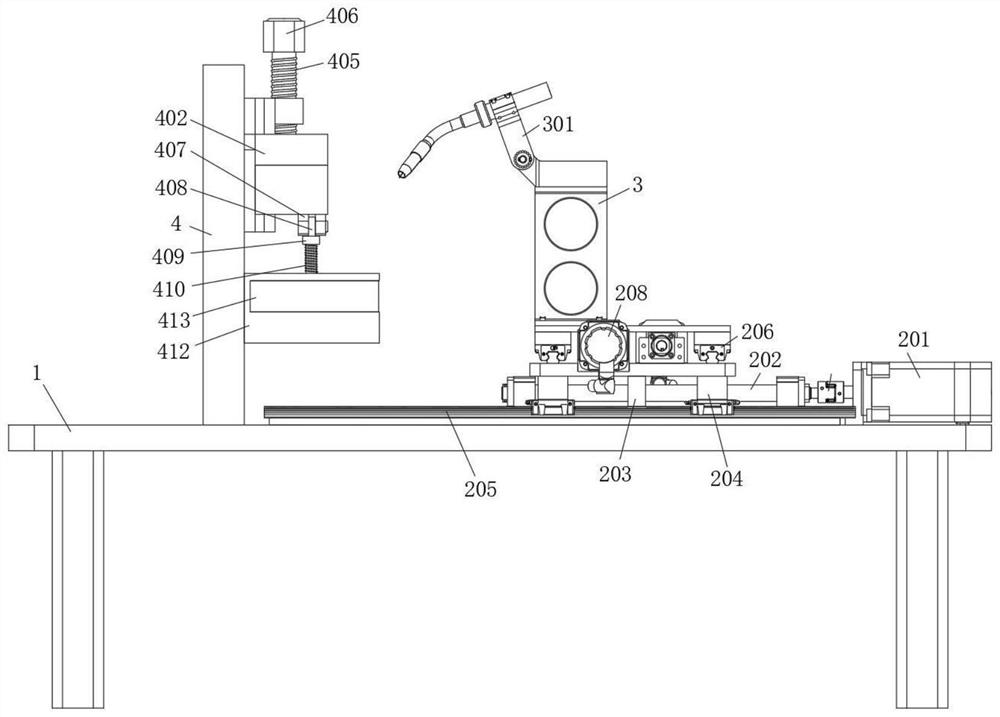
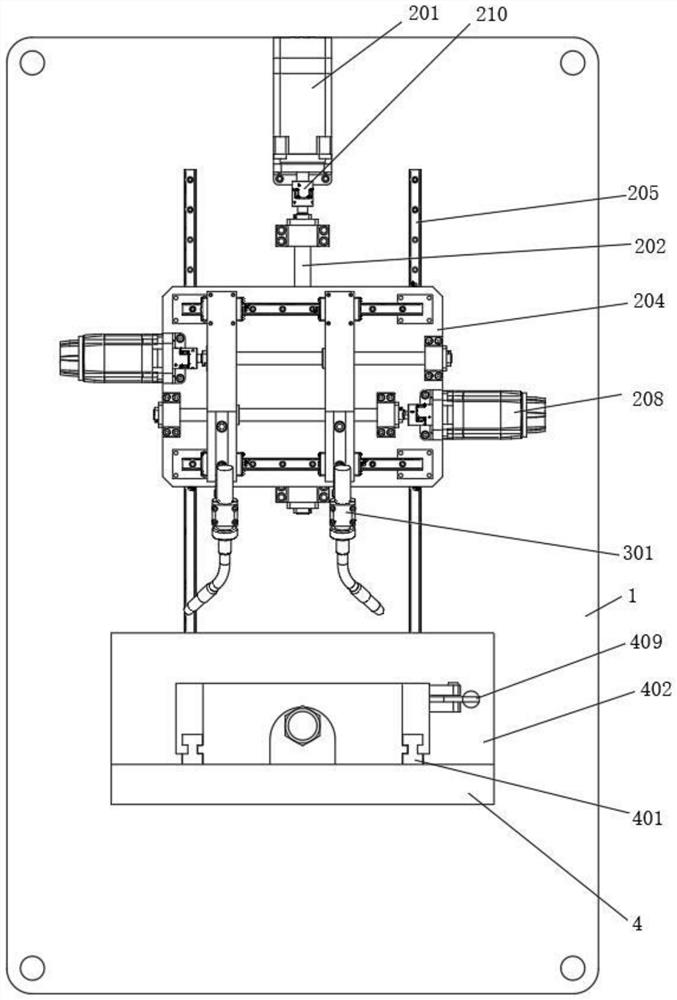
[0029] refer to Figure 1-5 , a fixing device for welding AC capacitor terminals, in order to enhance the applicability and flexibility of use of the fixing device, and improve the stability of the overall welding, a support platform 1 is provided here, and the top of the support platform 1 is provided with a bump The top of the support table 1 is provided with a mobile welding structure 2 and a vertical plate 4. In order to improve the efficiency of welding, a capacitor fixing structure for simultaneously fixing multiple capacitors is provided on the vertical side of the vertical plate 4 here. In order to facilitate welding tools Flexible use, the terminals can be welded at multiple angles, so as to ensure the firmness of the capacitor terminal welding. Here, a support plate 3 is fixedly connected to the top side of the mobile welding structure 2, and the top of the support plate 3 is rotatably connected to a movable fixed head 301 ;

[0030] The capacitor fixing structure i...

Embodiment 2

[0034] Such as figure 1 As shown, this embodiment is basically the same as Embodiment 1. Preferably, in order to play a certain protective role and not hinder the function implementation of the capacitor fixing structure, a hollow protective shroud is fixedly connected to the bottom side of the pressure plate 402 here. 403 , the lowest point of the protective shroud 403 is higher than the balance guide block 408 .

[0035] In this embodiment, some components of the capacitor fixing structure are protected by the protective shroud 403 to prevent them from being damaged by external factors, thereby prolonging the service life of the components.

Embodiment 3

[0037] Such as figure 1 As shown, this embodiment is basically the same as Embodiment 1. Preferably, in order to facilitate the screwing of the second threaded rod 405 and prevent the second threaded rod 405 from breaking away from the fixing ear 404, an end cover 406 is fixedly connected to the top of the second threaded rod 405 , and the width of the end sleeve 406 is greater than the diameter of the second threaded rod 405 .

[0038] In this embodiment, the threaded rod 2 405 is driven to rotate by rotating the end sleeve 406 , thereby realizing the pressing down of the pressing plate 402 .


PUM


Abstract

The invention discloses an alternating current capacitor terminal welding fixing device which comprises a supporting table, a protruding block is arranged at the top end of the supporting table, a movable welding structure and a vertical plate are arranged at the top end of the supporting table, and a capacitor fixing structure for fixing a plurality of capacitors at the same time is arranged on the vertical side of the vertical plate. The top side of the movable welding structure is fixedly connected with a supporting plate, the top end of the supporting plate is rotationally connected with a movable fixing head, and the capacitor fixing structure comprises a vertical guide rail, a pressing plate, a fixing lug, a second threaded rod, a U-shaped warping rod, a balance guide block, a pressing rod, a reset spring, a bending rod, a limiting plate, a multi-station fixing plate and a connecting rod. According to the capacitor terminal fixing device, the capacitor and the terminal of the capacitor are fixed through machinery instead of manual work, stable operation of welding operation is guaranteed, the multiple capacitors are fixed at the same time, lasting operation of the welding operation is facilitated, the welding work efficiency is greatly improved, and the use requirements of people during capacitor terminal welding are met.

Description

technical field [0001] The invention relates to the technical field of capacitors, in particular to a fixing device for welding AC capacitor terminals. Background technique [0002] Two conductors that are close to each other, with a layer of non-conductive insulating medium in between, constitute a capacitor. When a voltage is applied between the two plates of the capacitor, the capacitor will store charge. The capacitance of the capacitor is numerically It is equal to the ratio of the amount of charge on a conductive plate to the voltage between the two plates. The basic unit of the capacitance of a capacitor is Farad (F). In the circuit diagram, the letter C is usually used to represent the capacitive element, and the capacitor is used when it is in use. , It is often necessary to solder its terminals on the motherboard. With the continuous development of technology, more and more capacitors are used. [0003] Although capacitors are widely used, there are problems in th...

Claims


Application Information

Patent Timeline
Patent Type & Authority Applications(China)
IPC IPC(8): B23K37/04B23K101/36
CPCB23K37/0443B23K2101/36
Inventor 谷玉祥朱英文
Owner 铜陵市科峰电子有限责任公司
Learn More